

Upgrading my Networking Gear (2022.2)
It’s been a few months since I transitioned my home network from something built around a ‘gaming router’ which is nothing more than a glorified do-it-all device to a setup comprised of a whole bunch of dedicated devices that each do one very specific thing. I didn’t have a particular brand in mind when I set out to explore this - only that I specifically didn’t want Ubiquiti. Primarily for cost-reasons, my search started with TP-Link’s Omada system and while I briefly poked around other options (notably, NETGEAR’s Insight) but my search effectively ended with TP-Link since it was affordable and more importantly I was able to actually order all of the equipment I wanted in a timely manner.
I ended phase one with some hopes for the future might entail for my network and while I don’t think the network has reached it’s ‘final form quite yet’, there have been some interesting developments worth taking a moment to look at.
Networking Series
This post is part of a series, check out the other posts!
Quick Links
What's new?
My initial (2022.1) network upgrade was straightforward: switching from a ‘do it all’ gaming router to a setup where each piece of equipment was built around performing a singular task. Over the last few months I’ve chipped away at some incremental upgrades and as I inch closer to ‘final form’, those upgrades loosely fall into one of three broad categories:
New or improved functionality
Redundancy
Organization, tidying and general ‘quality of life’ improvements
Here’s a snapshot of where we started - functional but a bit chaotic:
The starting point: here, I thought I had a ton of space left on the rack. Rookie mistake…
New gear
2.5GbE Switch
As I noted in the last update, I was wanting to get a 2.5GbE switch - this would give my ‘lesser’ computers a somewhat-fast access to the NAS. For better or worse, the selection of available [TP-Link] 2.5GbE switches is pretty sparse:

(July 2022) Not a lot of options available for 2.5GbE switches…
Currently, the TP-Link TL-SG3210XHP-M2 is the only option for a 2.5GbE switch and for better or worse, this switch does appear to be designed with the ‘all the checkboxes’ mindset: rack-mount, all 2.5GbE ports, POE on all ports (240W total budget) and 10G uplink. Being feature-rich, it unfortunately ends up being pretty expensive (and was hit pretty hard by shortages).
It also has two fans which are quite loud — thankfully, during normal operation, they don’t seem to run at all — I’m not currently using POE and I’m only using a few ports so I don’t expect the fans to be a real issue. Ideally, I wanted fan-less to reduce the number of moving parts that can fail but I suppose if they do fail (or if I get annoyed at the power-up noise), that a Noctua A4-20 PWM swap would resolve my problems.
I have a specific set of machines that I wanted to put on the 2.5G network and while most of them already had 2.5G networking built-in, I picked up a few 2.5GbE USB-dongles for the machines that didn’t.
Fiber
A little while back we had an ISP leave a pamphlet on our door letting us know that they were running fiber-optic through our neighborhood. They were going to run the fiber through our neighborhood regardless (to feed a new subdivision being built) and the cost to get it installed was the magical price of free so this was a no brainer. Even if we eventually change ISPs, by opting in now, we can get the infrastructure in place for down the road. Initially I thought that we would be a fiber-to-the-curb (FTTC) setup, but it turned out to be fiber-to-the-home (FTTH).
For our location, the available residential fiber service is the same (1000Mbit down, 30Mbit up) as our existing cable service but I’m hoping that by switching to fiber, we can avoid any weather related noise/performance issues. One additional ‘benefit’ of the switch to fiber is just how much more compact the equipment is: my cable modem isn’t massive by any means, but the optical network terminal (ONT - roughly the equivalent of the cable modem, but for fiber) is so much smaller which is handy since I magnetically mount this secondary-equipment to the side of my rack.
My old cable modem, left, versus the new fiber ONT. It’s not even close. In fairness, the old cable modem has a built-in router as well, but I never wanted that functionality in the first place.
More access points
While I don’t directly spend a lot of time on Wi-Fi since almost everything has a hardline connection, I do have lot of smart devices and I wanted to ensure that the reception was great around the house. For the time being, I'm sticking with Wi-Fi 5 (802.11AC) for a few reasons:
The overwhelming majority of my clients are IOT 2.4GHz Wi-Fi 4 (802.11N) devices so there’s no pressing need for living on the cutting edge
For now, for my purposes, Wi-Fi 5 speeds are more sufficient for browsing on laptops and phones; only a select few of my existing candidate devices even support Wi-Fi 6
I can save some money (for now) using older gear
For the time being, I went with five access points:
1x ceiling-mounted ‘normal’ unit - I went with the EAP225. While there are higher-performance models, I went with this purely because it was on sale and I knew that I was planning on having multiple APs for coverage.
1x outdoor unit - I went with the EAP 225 Outdoor. This was an easy choice because it was the only available option!
3x wall-units - I went with EAP 235 Wall. Here I went with the 235 model vs the 225 model because of the downstream 1GbE ethernet ports versus just having 100Mbit ports
The ceiling and outdoor APs are pretty straightforward: one acts as my ‘primary AP for the house’ and the other provides dedicated coverage in our backyard. The neat bit happens with the in-wall APs.
The -Wall units provide a three downstream ports! In a spot like my living room (by the TV), was initially considering running a bunch of ethernet to the area (three lines actually: media player, Chromecast and Fire stick) but with an in-wall AP, I can run a single line and be able to connect my devices and get a bit more Wi-Fi coverage? That sounds great! The same logic applied to getting network to the shop and upstairs to the teleconference room.
Cell booster
Where we live, there are only (current) two cell towers (and neither is directly our carrier’s tower) and both towers are fairly far away, so needless to say, reception isn’t great. Spending most of my time underground in the office probably doesn’t help much either. Signal wise, we get -108dB to -118dB in our basement office which is pretty bad. Stepping outside, the signal hovers around -95dB which is plenty. On a Black Friday whim, I bought a basic cell booster. I was really expecting it to be a gimmick and to return it shortly afterwards but it has been a total game changer.
Since I wasn’t expecting the booster to perform as advertised, I only did a temporary installation where the ‘outside antenna’ was actually in my garage (but at least pointed at the cell tower) and I quickly put the inside antenna in the furnace room in our basement. With the booster temporarily installed, things were definitely improved: it wasn’t great but the signal was at least stable and much more usable. With a successful test, I played around with a few different cable configurations before the final installation.
The difference between RG6 and RG11 was very eye opening:
I knew that going from 60ft to 100ft of RG6 would have more signal loss but wasn’t prepared for just how much that would impact the final signal
I was also totally blown away that the 100ft RG11 would outperform even the shorter 60ft RG6 and by such a definitive margin
Like, on paper, I can see that RG11 has half the signal loss of RG6 but it’s a difficult thing to '‘visualize” until everything is installed and you can run some tests.


I haven't had a lot of time to really play with the positioning and angle of the inside-antenna, but now, our signal is -80dbA to -109dbA which is much more usable. At the moment, I mounted the inside-unit on a piece of plywood and using switchable magnets, have it ‘mounted’ in my mechanical room. I have quite a bit of slack available to relocate the unit as well.
More redundancy
Cellular modem
Recently in Canada, we had a major nationwide service outage and while my phone wasn’t affected, my cable internet was. For me specifically, the outage was just a minor inconvenience — I had already planned on being in the office that day (and the office connection wasn’t affected) but my wife’s day was mostly a write-off.
I’ve always fancied the idea of a WAN failover but it was finally this outage that pushed me to actually look into what it would take to implement a failover system. In short - I’m getting too old for this kind of crap. In an ideal world, each service would be handled by different provider:
Primary internet provided by telecom A
Phone & data provided by telecom B
Some form of backup cellular by telecom C
Due to lack of meaningful telecom competition in Canada, it’s not really practical (read: it’s needlessly expensive) to spread your services around across multiple providers - in fact, the telecoms go out of their way to incentivize you to bundle services together. As such, the best option for me, for now is:
Primary internet via Fiber provided by telecom A
Phone & data provided by telecom B
Cellular backup provided by telecom B
It took me a grueling 5 hours+ working with my telecom to find a plan that suited my needs; the specific individuals I worked with were super friendly and helpful, the entire process is definitively not fun.
Equipment-wise, I went with a NETGEAR LM1200:

NETGEAR LM1200
According to NETGEAR, this is certified to work with AT&T, T-Mobile, Verizon, and UScellular. Not compatible with Sprint — this makes decision making pretty easier for Americans ;)
For Canadians (from direct personal experience) this works with Telus (which means it will work with the flanker brands, Koodoo and Public Mobile (which literally run on the same network)
Supported bands:
LTE : 2, 4, 5, 12, 13, 14, 66, 71
3G Bands: 2,4,5
Note that this modem is 4G/LTE only.
I did a quick survey of the different bands used by Canadian carriers and compared them against what the LM1200 supports. Technically speaking, you’ll only need one supported band for it to ‘work’ but in practice, you’ll probably want at least a few numbers to line up.
Theoretical compatibility (July 2022) for the NETGEAR LM1200 for various Canadian carriers.
For the most part, the LM1200 has pretty broad support across Canada (except maybe Videotron). Obviously, you’d need to double check with your carrier (or take a gamble) but generally, the more overlap there is between the bands used by your carrier and the bands supported by the LM1200, the better your odds.
The data was what I could find as of July 2022 but through acquisition, infrastructure investment or cooperation, carrier support for bands can change over time. One thing to note: I made the table with 4G/LTE in mind; in a failover scenario, switching to 3G, while literally better than nothing, isn’t really my intended goal. As such, you’ll also need to make sure that your carrier (and plan!) support 4G/LTE otherwise you’ll be limited in compatibility (or performance).
Verifying compatibility
You would be correct in thinking that it would be a smart idea to verify with your carrier on the compatibility of the LTE modem before ordering the device. However, based on my experience (which, admittedly is a single data point), their [very well intentioned] verification process mostly amounts to the same thing you can do yourself: they check the theoretical band-compatibility and then do some searching for product reviews…
It may be less hassle to simply buy the cellular modem, walk into a store (if applicable) and have the store techs verify right there and then if it’s compatible.
When talking to the carrier, the key thing to ask for when talking to your carrier is to get a tablet SIM card — be very explicit about this (otherwise you’re potentially getting a whole new phone line — I made that mistake and had to call back). Prices per carrier will vary (and they will try and shuffle you towards the higher priced data plans — of course); in my case, I was able to get a $0/month tablet-only SIM which draws from the same data-pool as my phone plan. But only after I upped my plan to one of the pricier options (of course).
WAN Failover
One awesome feature of the LM1200 is that it has the built in ability to do WAN failover out of the box so you don’t even have to have a ‘fancy’ network setup to benefit from this. The modem has two ethernet ports and by connecting this to both your existing-router and your existing-modem, this device is able to detect the primary internet connection going offline and automatically switch you over.
How to connect the cellular modem for built-in WAN failover
The unit is also able to send you text messages to let you know about different states:
switching to cellular, switching between 3G and 4G, roaming etc.
approaching (or exceeding) a data cap: you can define your data limit and warning threshold in the management portal
Note: if you have a tablet-only SIM card, note that you won’t be able to take advantage of the text alerts.
Since my network setup gives me the ability to manage multiple WANs in a failover scenario, I’ll make be using that instead of the built in capability from the cell-modem:
Configuring multi-WAN with failover in Omada
I did a bit of quick testing of the failover to make sure things were mostly behaving as expected: I unplugged the primary internet connection, waited for the router to switch to the cellular and then restored the primary connection to verify that it also switches back.
Fail-over sequence
We start off with the initial ping coming back with 4-5ms
After disconnecting the primary connection
The request briefly times out and cuts over to the cellular with a response time of 30-50ms
On the portal, the link-down and offline state is picked up within 60 seconds (as configured)
After restoring the primary connection
The portal picks up the restoration within 60 seconds (as configured)
The pings briefly time out before switching back to the primary connection with a response time of 4-5ms
Improving the signal for the cellular modem
Although I have a cell booster here in the basement where the cellular modem resides, because I was mounting the modem on the ‘far’ side of a metal rack, I opted to get a cellular antenna to give the modem the best chance at working well. I went ahead and ordered a cheapo set. There are a bunch of different styles you can get at different price points; for the most part, I think you just want to match support for the cellular frequencies you need verify the antenna comes with the correct physical connectors (TS9 in my case).
Physically installing the antenna
A heads up that plugging in the TS9 connectors is an odd experience: there’s no real feedback on the insertion process so you can’t readily tell how well seated (if at all) the connector is. It’s not clear when the plug begins to install and there’s no feeling to indicate that you’ve fully installed the antenna. And making that initial connection required an almost-concerning level of force. Note: even fully installed, the plugs do not bottom out. Stop pushing lol.
Once you have your antenna installed, you get to play with the antennae orientations and figure out particular positioning of the antennae gives the best results. Since this involves physically changing the direction/angle of the antennae, I recommend taking photos of each orientation (use a sticky note with a label in the picture so you can reference which pattern) and running some tests for each orientation. Having the pictures is handy once you’ve identified on which particular pattern is best, you can go back to it.
To collect the data you’ll need to log into the cellular modem (the hardcoded IP is 192.168.5.1) and navigate to Settings —> Mobile —> Status Details. You’ll want to pay attention to a few things:
The RSRP, RSQR and RS-SINR values — this will give you an indication of signal strength
The Cell ID, channel number, current radio band — to keep all of the comparisons even, you’ll want to make sure you’re only noting values when connected to the same tower
The values on the status page automatically refresh and I made note of all of the values at regular intervals; collect a bunch of data points for each antenna position — repeat this until you’re sick and tired of collecting data.

Here’s an example subset of data points I collected for my specific configuration:
Signal quality data points for each antenna position. Don’t forget to collect data without the antenna plugged in as well (this helps you verify that that the antenna is actually connected properly)
In all cases, the biggest numbers are best, so in the above data sample, antenna placement #4 was the most ideal with #2 coming in as a close second. I only did a few spot tests but there was a significant change in speed-test results between the ‘best’ and ‘worst’ positions (30mbit vs 3mbit).
Tidying everything up
The biggest improvement with the network is just how much tidier everything is. I had delayed (procrastinated?) on making progress on this since I wanted to get all of the in-rack equipment first (reasonable) and all of the far away endpoints wired up and installed (more procrastination than anything else) — it’s a daunting task to do on short order as I don’t often have a huge downtime window to really take everything apart and ‘do it right’.
Looking back, I’d say that there were a few major steps/themes in the over cleanup of the network:
Adding another PDU
Magnet mounting everything
Finally committing to using patch panels which let me
Use color coded cables
Redoing the cables to be “better length”
Labeling all of cables
Organizing all of the cables running across the [drop] ceiling: grouping, securing and labeling them
Additional PDU
I had started the rack with the idea that each component would live on an individual power switch - this would make it braindead easy to force-reboot any device, at any time without needing to log into a management portal and initiate a reboot or whatnot. That first PDU was the Pyle Pro PDBC70 and it’s a great unit that just does what you need it to do without any fuss.
While I had initially thought to get a second unit, I wanted to eliminate having an additional USB charger on the rack (because it's where I occasionally charge some extra devices), so I looked around for a PDU with front-facing USB ports. I ended up getting the model with front-USB, Pyle Pro PDBC90. On paper, this looked like a no-brainer: you give up one switched-output to get four front-facing USB ports. Sounds great, right? Wrong. It’s a horrendous PDU to neatly integrate into an existing rack and it’s a matter of time before I swap it out for another basic PDBC70 unit. Let’s walk through the disaster train:
When you initially look at it, it looks like it ought to take up 1U (3-screw hole spacing). Nope. Due to a combination of distance-from-edge that the holes are inset and the needlessly large frame of the unit, it ends up being 1.5U (5 screw holes). But wait, there’s more:
The unit comes with rubber-feet (even though it’s marketed as a rack-mount PDU) and those feet extend so far below the PDU that it pushes the effective size to 2U (5.5+ screw hole). But wait, there’s more:
You can simply remove the feet with a screwdriver right? Wrong. You can remove three of the feet easily with a screwdriver. To remove the fourth, you have to take the PDU apart to see that it’s actually a nut and bolt holding the rubber foot. But wait, there’s more:
The PDU is using that nut and bolt as a common connector to join a bunch of wires together to the electrical ground.
So, after a bit of electrical surgery to join those wires, you can finally have an aesthetically disgusting PDU you can put on your rack. Remember that point about the needlessly large frame? This means that your PDU now has a forced gap between it and the next unit. Sure it improves airflow, but that should be my decision, not something forced upon me by stupid design.


The future doesn’t bode well for this PDU…
The next time I feel like tinkering with the rack, I’ll probably end up getting a second PDBC70 and I’ll magnet-mount a USB charging station to the side of the rack so that I have ‘convenient’ USB chargers on the rack. Save yourself the hassle (or at least be fully aware) and skip the PDBC90.
Magnet mounting everything
So one really nice thing about my build is that I can just simply pop the top off and I have direct access into the belly of the rack but when I’m all done, I can put the top back on and it becomes a nice sturdy, flat surface that I can put stuff on. The thing about nice sturdy, flat surfaces is that they inevitably end up accumulating all kinds of crap on them.
From before, I really liked having the cable modem mounted in its own box, magnetized to the side of the rack so it was simultaneously out of the way, but I could still lean over and see the status light. With the change to fiber and the addition of the cellular modem (with its own magnetic antenna), it was a no-brainer to continue the practice of magnet-mounting everything. Thankfully every piece of equipment makes it pretty easy to get mounted up.


Magnet mounting
Most of the miscellaneous network devices have holes for wall-mounting so it was just a matter of mounting magnets to the backside of some plywood.
I went with some cheapo magnets and I using a 1-1/4 Forstner bit, I hogged out a 1/4” deep recess for the magnet. I secured the magnet to the plywood using a #6 1/2” screw.
Patch Panels and Colored Cables
In terms of tidying things up on the rack, this was a huge. Previously, I had cables coming in and out every which way and while everything worked, it was horrendous. Some of this is due to the design of my computer desk where the desk itself provided network connectivity — a byproduct of building it for our previous place.
For the longest time, I put off having a patch panel as I saw it as form over function, but there is value in having your cables organized so I committed to at least giving it a try. If I could have my way, I would have wanted a 48-port patch panel that used couplers or I would even have considered an empty 48-port panel and just bought couplers (then I could even color coordinate the jacks!) but they don’t really make the former and the latter was more costly than I felt like committing to. So I went with a pair of 24-port panels.
Why not a punch down setup?
I think this mostly comes down to a personality/perspective thing: I still expect to be able to tinker inside the rack while everything is live and running — so I need to be able to connect, disconnect and move things around (with very little wiggle room) so going with couplers makes things so much simpler.
Once I had the panels, it was a 'fun' task of figuring out what should go where. In addition to 'keeping related cables together' and by proxy, trying to manage visual complexity of the cable runs, I needed to also juggle the colors of the cables as not all cables were available in every color/length combination and then as icing on the cake, I had to juggle the cost too as not all color/length combination was priced the same. As for colors, I settled on the following scheme:
White - WAN
Blue - Interconnects between devices
Green - APs
Red - anything NAS
Purple - IP cameras
Orange - 10G clients
Yellow - 2.5/5G clients
Black - 1G clients
I pretty much used all of the colors I could readily get available; if I suddenly discover a need for another color, I can use blue for the WAN connection as well and then white is an available color. I happened to go with slim cables but that wasn’t a major consideration.
A note about using slim cables
From a data transmission perspective, you should be fine to use slim cables; the only potential concern is running POE over the slim cables: the smaller cables don’t have as much heat capacity. In my particular case, I ran slim-cables on the patch panel to the POE injectors and ran standard cables from the injector (after they were energized) to the devices.
My patch panels supported having the cables zip-tied down to keep them from moving and I initially zip tied everything down and it was wonderful until I wanted to move a connection down a slot — so the zip ties had to go.
Better length cables
Compared to what I see in a lot of “look at my network rack” shots, my cables are much longer than they ‘need’ to be. This is a big lesson learned from me as I’ve gone my entire computer-life with exact length cables but having the slightly longer cables is a necessary evil if you want to be able to pull the patch panel out and tinker: you simply need that extra slack.
A humorous OCD dilemma
When connecting patch panel ports to their associated switch ports, since every pair of ports is a different distance from each other (you know, due to, uh, reality) you have two OCD choices: you can have every connection be the exact length needed — but now your cables are all non-standardized-length, or you can standardize your cables but some/many/all of your cables will have slack in them. Best not to think about it ;)
When I rewired everything, I actually ended up putting quite a bit of slack in the cable runs feeding the back side of the rack — I want to be able to roll the cabinet a few feet out of the way if I need to get to my computer, or the breaker panel, or I just want to spin the rack around to access everything from the back side. As it is now, the rack has three different ‘tethers’:
Power connection from the UPS to the wall outlet. In a pinch, I could always play the extension cord game to remove this constraint
The mass bundle of cables coming down from the ceiling into the rear of the rack: when I cleaned up the cables, I standardized the amount of slack in these cables to give me a few feet of range
My computer desk directly plugs into the rack (through the back); it doesn’t yet make sense to run this through the ceiling so for the meantime, I doubled the length of the three cables so that I have plenty of room to roll the cart away
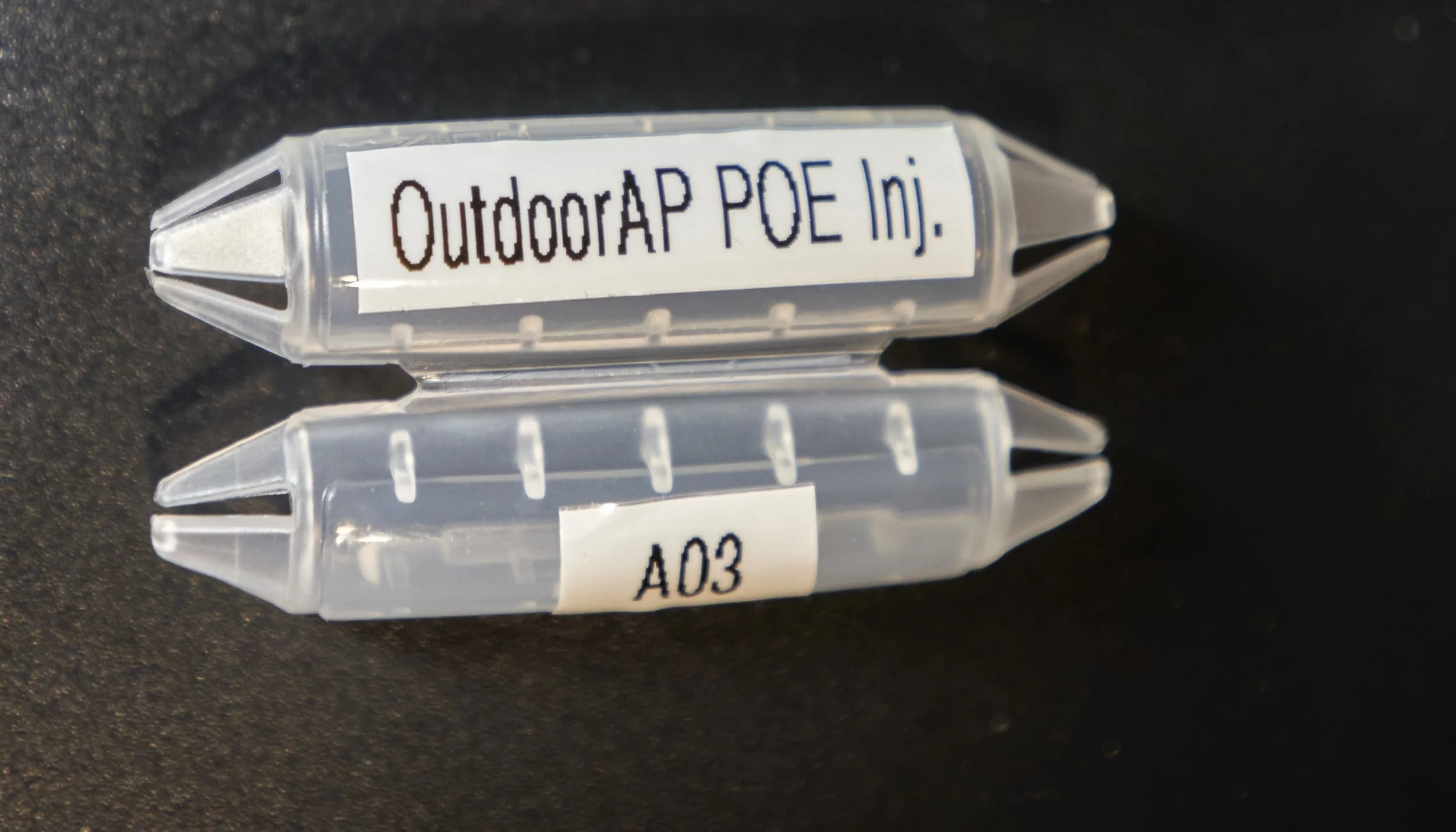
Labeling cables
A long time ago, when I finally got around to taming the mess of cables behind my desk, I wanted to find a way to label cables that was easy to apply but equally important, was easy to change/update. I stumbled upon Cord ID from a company called Dotz and fell in love: the magic of this labeling system is that you can easily remove and replace the entire tag easily - handy if you want all your tags reading the same way or if you want to update a cable. Being made of plastic, label-maker labels stuck to it very well and the design allows you to label almost any cable you are likely to come across (up to about 5/16 diameter) — this means that you can label up to AWG16 power cords and every so often you can push your luck and even get it on a AWG14 cord.
Thanks to covid and then the manufacturing and supply crunch, they were out of stock for quite some time. I got into a regular chatting cadence with the designer and with a ton of patience, they were finally restocked. Needless to say, I bought a whole bunch.
Using these tags, I labeled both ends of most of the cables; the only exception would be the actual patch cables which I only labeled at one end. This was in an effort to conserve the precious tags but also because the majority of my devices are not setup depend on being plugged into a specific port on the destination switch — I just grouped them together for coherence and aesthetics so really, I only needed to know which port on the patch panel to plug into.


After doing an initial pass of labeling, I went back and tweaked some of the labels to be more generic i.e., ‘A02 EAP225 1G’ became ‘A02 Main AP 1G’).
USB ports for the NAS
I had some free space on my patch panels so I used the opportunity to swap out a couple of ethernet jacks for USB keystones; I ran USB-A to USB-A cables to provide connectivity to the USB ports on both of my NAS units. As a bit of a longer-term goal, I want to be able to quickly dump data to-front the NAS by directly connecting a device to the USB ports conveniently located on the patch panel.
USB3 keystones in the patch panel run to the ports on each NAS allowing me easy access to quickly connect devices to the NAS
Tackling the cables in the ceiling
We are lucky to have a drop ceiling in the basement which makes it super convenient to run and hide cables every which way but it very quickly becomes a huge mess where almost every cable is a generic, non-descript black cable. While everything is still vaguely fresh in my mind, I wanted to get this disaster under control.

Pre-running stub cables
So that multi-day internet outage we just had? That came in pretty handy, giving me the time to finally get started on this.
The biggest “challenge” was that not all of the cable runs were in place yet but I still wanted to make some progress. As a compromise, I opted to pre-run cables from the rack to a common collection point, roughly in the direction where the cables would need to be run anyways, allocating enough runs for all of the devices I had planned. I ended each of those partial cable runs with a coupler so that we could simply carry on from that point when we were ready to the rest of the installation.
Most of the devices on my network are ‘far away’ and I have cables snaking across the drop ceiling to the network rack. At some point, they need to transition from the ceiling down into the ‘visible space’ and into the rack. I didn’t want to just have an open hole in the ceiling tile because over time, chafing would cause the ceiling tile to crumble so I wanted to get some kind of a bushing to allow the cables to transition through nicely. The problem though is most cable passthrough bushings are friction-fit and designed for desks (where gravity will hold the bushing somewhat in place); for a ceiling, I needed a bushing that would secure itself to the ceiling tile.
I found a pretty clever spring loaded cable passthrough from a company called Construct Pro. I think it’s somewhat pricy but it uses two spring-loaded tabs that clamp onto the ceiling tile (or drywall, etc.) to keep the passthrough from slipping in either direction. With a 2” inner diameter, you can feed a lot of cables through it; with the number of cables I was planning on passing through, I might have been able to squeeze it all into one passthrough but thinking down the road, if I added much more, I would need to get another passthrough.
It might not be immediately obvious, but to install another passthrough (down the road), I would have to remove the ceiling tile to drill the appropriate hole and to that, I would have to disconnect everything. I’d rather not have to do that in the future, so I just went ahead and put in two passthroughs now. One advantage of having two is that I can use it to collate similar types of devices (i.e., all of the access points will route through this passthrough), or devices coming from similar locations (i.e., all cables coming from the front of the house go through this passthrough).
A pair of cable passthroughs allows me to group the different cables going to the network rack together
Since I have devices spread out all over the house, I have cables running every which way across the ceiling so using a combination of conduit clamps, plastic cable clamps, Velcro & nylon zip ties, I was able to group all of the cables loosely together. Across the ceiling, I ended up labeling a few spots that indicated where a given bunch of cables were going (i.e., “shop”) or what individual cables were (i.e., “Fiber line”).


Since I was going through this much effort, I went ahead and ran another passthrough to the other desk in the office to directly connect that computer to the network — previously it was connected via my desk (meaning that there have been a couple of network cables running across the floor for a while.
Thoughts and reflections
Labeling
Once I started plugging things into the rack, I had a really big dilemma: everywhere I looked for inspiration for what a network rack ought to look like showed roughly the same layout but to me, they were all missing the single most important thing — labels. Sure, you can write things down on a piece of paper, or have a spreadsheet to track everything but:
To someone standing in front of the rack, where does this cable go? Where does that cable go? What about this other cable? What if you’re peering through the belly of the rack and wondering where ‘that dangly cable’ goes? What if you have a handful of identical-looking, nondescript, network cables that you need to feed now connect to the network? What if you unplug everything (say, because you needed to drill a new cable passthrough) and now you have to put everything back together, which cable goes to which port?
As someone standing in front of the rack, I want to know where any given cable goes from/to right now; I don’t want to find out in 10 seconds, I don’t want to have to go look up a list somewhere, I want to just look at the cable and know. Of course, labeling individual cables doesn’t mean you can’t have a master list somewhere as well!
Maybe it’s a matter of personality/use-case: I foresee the need to tinker in the network rack while everything is as live and/or have the least amount of downtime as possible, so I need to be able to know which cable goes where. I guess most rack setups are more ‘wire it once, never tinker with it’
The ultimate goal is to be able to unplug any cable at either (or both) ends and know what that cable does and where it’s supposed to go.
The Cord IDs by Dotz are a real game changer for this because it decouples the labeling process from the cord installation process: they clip onto cables meaning you can add, remove or update labels to wires after they are all wired in. If you have a bunch of cables, you can even unclip it to flip it around so that all of your labels read the right way. It’s great for extended runs of speaker wire running across the ceiling as well.

Maybe it's not a rack...
I never gave it much thought until recently, but an [obvious] big difference between my network setup and what I see a lot of in home-labs is that mine is mobile. Perhaps it’s a hold over of my renting days when it didn’t make sense to have a permanent (or even semi-permanent) installation but perhaps it’s more subtle than that. So perhaps my setup is more ‘mobile network cart’ than ‘permanently wired in rack’. Even now at this place, if I had a chance to redo everything, old habits die hard — I’d still make a mobile cart rather than have something affixed to the wall.
Perhaps it’s a perspective thing — I want to be able to glance over and see the network rack and having the rack on wheels means that maintaining and working within the enclosure is really nice — I can just spin the entire thing around and access the back side.
There is an aesthetic hiccup though: both the ‘not-perfect length’ cables and having a few cables running from my wall-desk to the rack is a bit unsightly. To get rid of the tether, I would have to install a wall plate by the desk, run the cables up the wall and then back down with the rest of the bulk-cables. I’m not there yet. I’ll revisit this when I do a rebuild/upgrade to the wall-desk.
Switches for everything?
I specifically went out of my way to generally not use the POE functionality in my switches (at least for the APs). At a high level, I explored alternative options because:
I didn’t have right number of POE ports,
On the right devices
When I initially did the setup
And I didn’t want to pay the premium to get POE on the switches that would have worked out
That was the original reasoning for not going with the limited POE ports that I did have at the time. By using POE injectors, I ‘lose’ the ability to manage this from a web portal, but I see this as a good thing: if I want a specific AP rebooted or turned off? I just flick a switch. No need to log into any portal and try and find the POE controls. To be fair though, I’ve not yet had a problem with any of the APs that necessitated me hard-rebooting them.
An indirect benefit that we don’t think of much is that it becomes extremely easy to run power-lean during an outage. We live in an area that seems to be more prone to power outages during storms and while everything is on a UPS, being able to very quickly power down devices ‘that don’t matter’ gives the NAS units as much time as possible to power down.
Gear Snapshot
As a snapshot in time, this is what we’ve got for now:
Router: TP-Link ER7206. There’s a cheaper ER605 model that is super popular (and I’d probably recommend for most people) but one of the things I specifically wanted to minimize was downtime caused by waiting for devices to power up. At the time, I didn’t know the roadmap existence of the ER8411 (and there’s no clear timeline for that launch), so I don’t have any regrets on getting the [perceived] higher performance unit.
Controller: TP-Link OC300. Similarly, there is a super popular and cheaper OC200 unit (or you could even go with a self-hosted controller for ‘free’) but I didn’t want to have to wait as much for ‘configuring’ and ‘saving’ actions, or for things to reboot. The OC300 has at least 2X the hardware performance under the hood so I just went with the higher performance unit. The controller has the ability to perform daily backups of it’s configuration and data - so I have a cheap SanDisk Cruzer (USB2) key plugged in to the front-port for that.
Rack options
Out of the box, the OC200, ER605 and ER7206 can’t be rack mounted but thanks to the power of 3D printing, you can get custom enclosures for them. You can get a wide variety of options: ER7206-only, ER7206+OC200, ER605+OC200, ER605-only. For my rack, I use the ER7206-only
Cellular Modem: NETGEAR LM1200. I didn’t spend too much time digging, but realistically, this appears to be the only real option for a standalone cellular modem,. There are a bunch of USB-dongle options and a whole bunch of router/hotspot options which I didn’t want — I was looking for a single-tasking device. I’ve only used it for a little bit, but so far I’m pretty happy with this. Hopefully, down the road, there is a 5G option…
Antenna: Bingu BFN00492. This was exactly what I was looking for - a single ‘thing’ that had dual-plugs and as a bonus, already came with a magnetic base. Some reviews suggested that the magnets are worthless and while it’s not great, it stays put when I place it on the side of my rack, so no complaints from me there.
Switches
TP-Link SX3008F - This is my top level 10G switch which I was actually really surprised at just how affordable this switch was
TP-Link SG3210XHP-M2 - Compared to the 10G switch, this 2.5G switch was quite expensive but it’s hard to directly compare since this is a POE switch as well. I’ve not done it yet, but I may do a fan-swap one day if they fail or if the power-up noise bothers me too much
TP-Link SG3428X - This is my main bulk-switch and it’s always at risk of running out of ports - 24 ports sounds like a lot until you start running hardlines to everything
NETGEAR XS505M - The price of this unmanaged switch has gone up a lot since I bought mine, but I use this exclusively as a port-multiplier for all of the 10G/NAS related connections. It has a fan (which hasn’t failed yet)
NETGEAR GS116PP - This switch too has gone through a substantial price increase since I bought mine; I use this exclusively to run POE for all of my cameras
Connecting to SFP+
Connecting to SFP+ was a new thing for me I found that using ‘for Cisco’ labeled cables and transceivers worked for me. For specific examples, I used these 10Gtek DAC cables and these 10Gtek SFP+ to RJ45 transceivers without issue.
Access Points. For the time being, I use the TP-Link family of Wi-Fi 5 access points specifically because I’m still waiting for the equivalent access points to become available with Wi-Fi 6E
TP-Link EAP225 - This is my ‘main’ AP and I use it with the included TL-POE2412G POE injector which allows me to very quickly reboot or disable the AP just by killing power
TP-Link EAP225 Outdoor - As the name suggests, this AP is purely responsible for providing a bit better coverage into our backyard. It did not come with an included injector so I had to buy a TL-POE2412G POE injector
TP-Link EAP235 Wall - I used these access points to simultaneously provide some 1G ethernet drops as well as boosting the Wi-Fi coverage. These did not come with an included injector so I had to buy the POE4824G POE injectors
POE for future APs
Looking ahead at some of the Wi-Fi 6 and Wi-Fi 6E APs, they will need a 2.5G or 10G connection to feed the AP. Granted, in my specific case, I imagine dropping down to a 1G connection will not have any meaningful performance hit, but just brainstorming, I will have a challenge of trying to get a 2.5G or 10G POE injector. Thankfully, it looks like Trendnet makes 2.5G (30W) and 10G (90W) injectors so that will be something I’ll have to use.
Powerline: NETGEAR PLP2000-100PAS. I don’t really have a need for this anymore, but should the need arise, I have a port on the patch panel pre-connected for use with this - I just keep a 15ft run cable wrapped on the back side of the rack.
Rack: StarTech WALLMNT12. This was the biggest capacity rack of this formfactor that I could find; I had the smaller 6U before so down the road, I may build a stand/cart that allows for both racks to be used together for pseudo-18U capacity. Although at time, I think I may seriously consider a more proper 4-post cart
Power : I use the horrible Pyle-Pro PDBC90 alongside the much better Pyle-Pro PDBC70 and running everything through the CyberPower CP1500AVRLCD UPS unit
NAS: I have both a Synology DS1817+ (with 10Gtek X540), Synology DS920+
Future plans
Router
Within the rack, the only major equipment upgrade I can see on the horizon is the ER8411 router — if it ever comes out. With 10G connectivity both up and down, I can scale with my ISP if they ever provide a higher-speed connection and on the local side, my entire stack will be 10G top to bottom.
From a redundancy angle, it looks like the ER8411 has provisions for a USB-based cellular modem and while I don’t have a need for it at the moment since I can just plug my cellular modem into one the 1G WAN/LAN port, that’s a nice to have — more options are better than less. For people not running a dedicated cellular modem, this could be a good use case for permanently tethering an older smartphone (assuming USB tethering works).

Wishful thinking
Right now I have two 10G switches, the TL-SX3008F (8x10G) but also an unmanaged XS505M (5x10G) — it would be neat to eliminate the unmanaged switch from my stack just to reduce the amount of utilization and clutter in the rack. Sadly, I don’t foresee the 16x10G switch being affordable anytime soon though (one additional consideration: the 16-port switch has a fan as well which is another component to fail).
Wi-Fi Access Points
I’d like to do a complete cut-over to Wi-Fi 6E (or even Wi-Fi 7), but only once all the different access-point formfactors support it. At this point in time, (within the TP-Link stable of products), there are only a two products on the roadmap: the EAP 690E HD and EAP 680E HD. Both access points have product pages but they indicate that the products are still in development with no confirmed release window.
In my case, it’s a no-brainer to go for the EAP690E HD just for the increase in simultaneous coverage, particularly for the 2.4G band which represents almost all of my IOT devices. One thing to note with these two APs is that you will need a 10G port to properly feed it — and I’ll have to get a POE injector (802.3bt PoE++) to power it.
Since I wanted to do a full cutover of all of my access points to Wi-Fi 6E (or newer) at once, it’s going to be a waiting game for the other form-factors (wall-, outdoor-) to support the newer standard.
At the time of writing (July 2022), only two APs are on the roadmap for Wi-Fi 6E support.
Miscellaneous Changes
-
I had originally mentioned that I wanted to break my network into three performance tiers (fast, medium, slow) and to properly support that with my current hardware, I would probably get a 2x10G NIC for the primary NAS. On the rack side, I’ve already provisioned a port (with the cable in place) for the second 10G line so at least it’s one less thing to think about down the road.
Officially, the secondary NAS doesn’t support network expansion and Synology has also severely limited what you could use with the USB port (i.e., 2.5G+ USB network cards) but it would be neat to explore what aftermarket options are still possible.
-
Once I can get the last few ethernet runs installed, I won’t have a real need for Powerline anymore — I had used them briefly at this house and the previous house but the switch to better wireless coverage has been a decent stop-gap. While I don’t expect to have a recurring need for Powerline, I left a port provisioned on the rack and have a cable run clipped neatly on the back side of the rack if the need ever should arise.
-
At the moment, the NETGEAR LM1200 that I am using for cellular failover is a 4G only device and I haven’t been able to find a similar type of product, but configured for 5G so that’s something I’ll be keeping an eye out for. It’s not a priority since the cellular infrastructure here isn’t even great for 4G, so it’ll be quite a while (I suspect) before the infrastructure upgrades get rolled out. At the moment, there are some 5G devices but they are all ‘routers’ or ‘wifi-hotspots’ which isn’t what I want for this application.
I suspect that if-when 5G ever gets a roll out in my area, the signal will be improved so that I won’t need to make use of my booster (which is capped at 4G anyways) but if not, those are some additional components that will need to be updated.
-
At the moment, I have the entire network stack served by a single CyberPower CP1500AVRLCD and while it’s great, I really like the idea of dedicated UPS units: one for each NAS unit and then one for the actual network components. I looked at getting rackable UPS unit (to reduce the amount of cable clutter) but getting a few tower UPS units is much more affordable. I think that whatever route I go, I will need to revisit the base platform for my rack (to give me physical space to place the units, without stacking them) at which point it might be time to consider a more substantial four-post rack.
Closing Thoughts
Since the initial cutover to more dedicated networking gear, I’ve added additional functionality (2.5G switch, filling out the APs), added resiliency in the form of LTE failover but best of all, I finally got around to organizing the cables — even though it feels like I’m still light-years away from a truly tidy setup.
I’ve been dreading tackling the cable clean up because I knew it wouldn’t be a “just do it quick” kind of task — it ended up taking me a few days to get everything tidied up to where it is now. Thankfully the internet outage lined up perfectly to give me the window I needed to do the last-mile disconnect, rewire, reconnect cleanup tasks.
Looking ahead, ‘small upgrades’ like swapping out access points for updated models as they become available are fairly straightforward and should be low-drama. What will be exciting (or stressful) is what is in store for the rack itself:
I’m at the limit of what I can fit with my existing 12U rack (thanks in part to the silly shape and design of one of my PDUs); I have another 6U unit (my old rack) that I could do some DIY to make an 18U+ setup or is this finally the push to transition to a ‘proper’ four-post rack (on wheels of course)?
I don’t really like how the cables come in through the back side of the rack as a mess. For the next major revision, I may add a 24P patch panel facing the backside just to clean up the incoming wires a bit more. This would also help a lot with letting me decouple the cart on demand
I’m pretty bothered by my primary PDU: having some front-facing USB ports was totally not worth the extra aggravation so I will probably ditch this in favor of something less dumb and hang a USB charger on the side of the rack with magnets
I think that the next major upgrade to this network setup will involve a more substantial 4-post rack — this would certainly give me additional room but also give me the ability to add new types of gear (some rack-mountable equipment explicitly requires 4-posts).
When I first started down this journey, I wasn’t sure if I was going to have regrets going with a “less hardcore” route like TP-Links’s Omada, but in the few months that I’ve used it, I can’t haven’t yet run into major limitations on what I can/cannot do (likely a by-product of lack-of-expertise) but for now, it seems like a really good fit for me.
For the time being, I’m in a pretty good steady state.
Network Upgrade (2022.3)
If something isn’t broken, that’s a good time to upgrade it right? I can’t leave well enough alone so follow along for the next step in my network’s evolution.
Network Upgrade (2022.1)
Read about my original transition from a consumer, ‘gaming router’ network to more specialized equipment.
Product links may be affiliate links: MinMaxGeek may earn a commission on any purchases made via said links without any additional cost to you.