

Build Log: LED Slat Wall
We’ve had Skype Station for a few years now and it’s been great: it gives Nicole a low maintenance and (fairly) reliable place to do her video calls (I say ‘fairly reliable’ since it’s also a bit of an AV guinea-pig setup for me) and can be a separate working space when needed. Since moving to this house, I did a minor refresh but most of the changes have been fairly minor. While the hanging-backdrop solution we have is pretty good, this is something I’ve been wanting to tinker with for a bit so while Nicole was out for the weekend, I set out to do a ‘quick turbo project’ (spoiler: it was most definitely not quick turbo).
Quick Links
Starting Point
With respect to the backdrop, not much has changed since I originally built Skype Station:
The actual hanging background is a 5x7 ‘shower curtain’ essentially
We used a pair of Jumbo Command Hooks to hang 1/2” EMT conduit on the wall. We using a combination of clips, twist-ties and string to hang the backdrop off the conduit
The original backdrop: bulldog clips, twist-ties and EMT conduit
When I built the original Skype Station, we were renting so I wanted to minimize the number of ‘holes in the wall’ so this setup worked great. In hindsight, if we were to do this again, I would opt for a wider backdrop — the wider the better. This way, we had more flexibility with regards to how we setup the camera to frame everything. Being 5’ wide pidgeon-holed me into a specific camera placement.
Goals and Objectives
At a high level, I wanted three things
This needed to be a fairly quick project — Nicole was out for the [long] weekend and I wanted to have it done by the time she got back
I wanted to cover most of the wall so that I could have flexibility for [camera] framing
I wanted to give it a ‘cool factor’ but without it being excessively distracting
It needed to be ‘fairly affordable’ for the given amount of ‘cool factor’ it provided
My dream scenario would be to have some TVs mounted as faux-windows on the wall — something like what Drew Builds did; I’d configure it either as three 55’s in portrait mode in a 1x3 configuration or perhaps four smaller 48’s in a 2x2 configuration. For the sheer awesome-factor, I could totally stomach the cost of buying some cheap TVs, but the ongoing electrical cost (and extra heat they put out) killed the deal for me.
To keep heat and power usage in check, I opted to go for a slat-wall with RGB strips. For strips, I specifically wanted to look at DIY strips using something like WLED rather than off the shelf strips from a company like Govee. While I haven’t specifically run into a lot of grief with off-the-shelf RGB strips per-se, I didn’t like that everything was dependant on cloud-connectivity. Being cloud-dependent has a few drawbacks:
You’re at the mercy of cloud connectivity
All your commands need to go up to the cloud and then back down to the RGB strip which then means
That you’re mostly limited to whatever lighting animations and configurations that are provided out of the box
Rough Design
This project is broken down into four phases:
Paint the wall a dark color. This provides a bit of a moody base tone
Make the slats. A lot of online videos have you use 1x2 strips but since I have an easy way to cut it, I’m just going to use plywood
Cut slots to accommodate the aluminum channel
Mount the slats and wire up the RGB strips
At the start of this project, I expected the process of making the slots for the aluminum channel to sit in to be the biggest hurdle. I debated between using a plunge router with a track, a router on a router table or just cheating and using the table saw to cut dados:
Plunge router: advantage that I can set the final depth once and just use the turret stop to do multiple passes; downside is that this is a herky jerky process and I didn’t have a lot of wiggle room to work with — I’m routing 3/4” slot on something only 1½” wide
Router table: the advantage here is that I would feel a lot safer slowly dropping the strip onto the bit and I was okay with figuring out how to mark start and stop points; the downside is that I didn’t feel entirely comfortable with the process of making progressively deeper cuts and landing the same slot again and again (likely just a lack of experience thing)
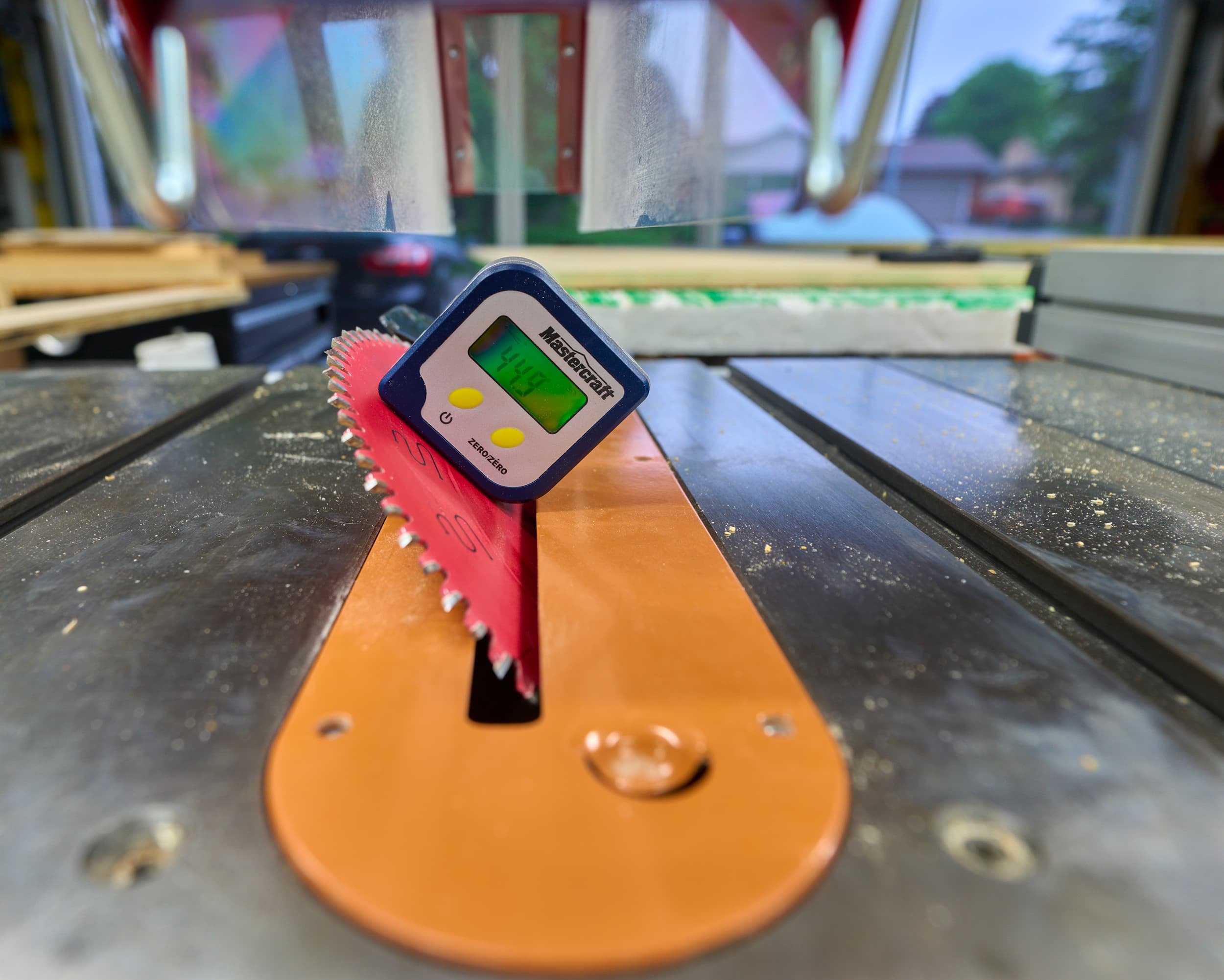
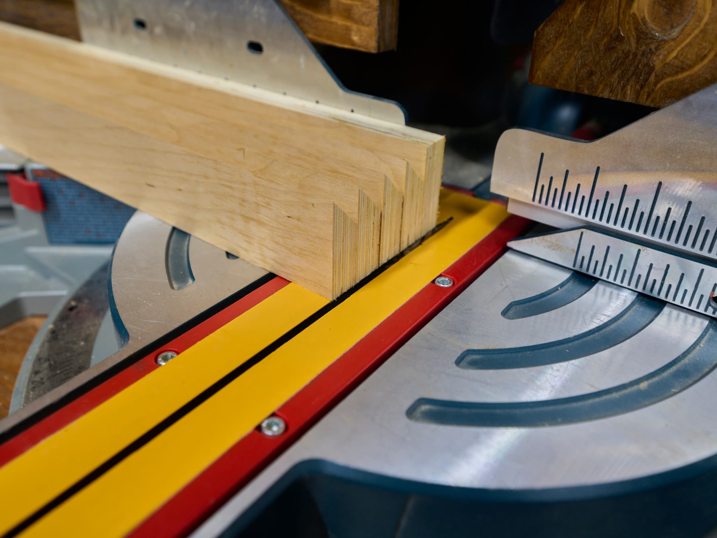
Table saw: mentally this is the easiest process — figure out where the slot needs to go and use the miter saw to cut above and below that point and use the table saw with a dado stack to cut the groove cleanly in one go; the downside is that I would waste time gluing it back together and there’s always the risk of the glue-up being slightly askew
For wiring, this was the easy part: my plan was to leverage solderless connectors and spade bits to wire everything up. #foreshadowing.
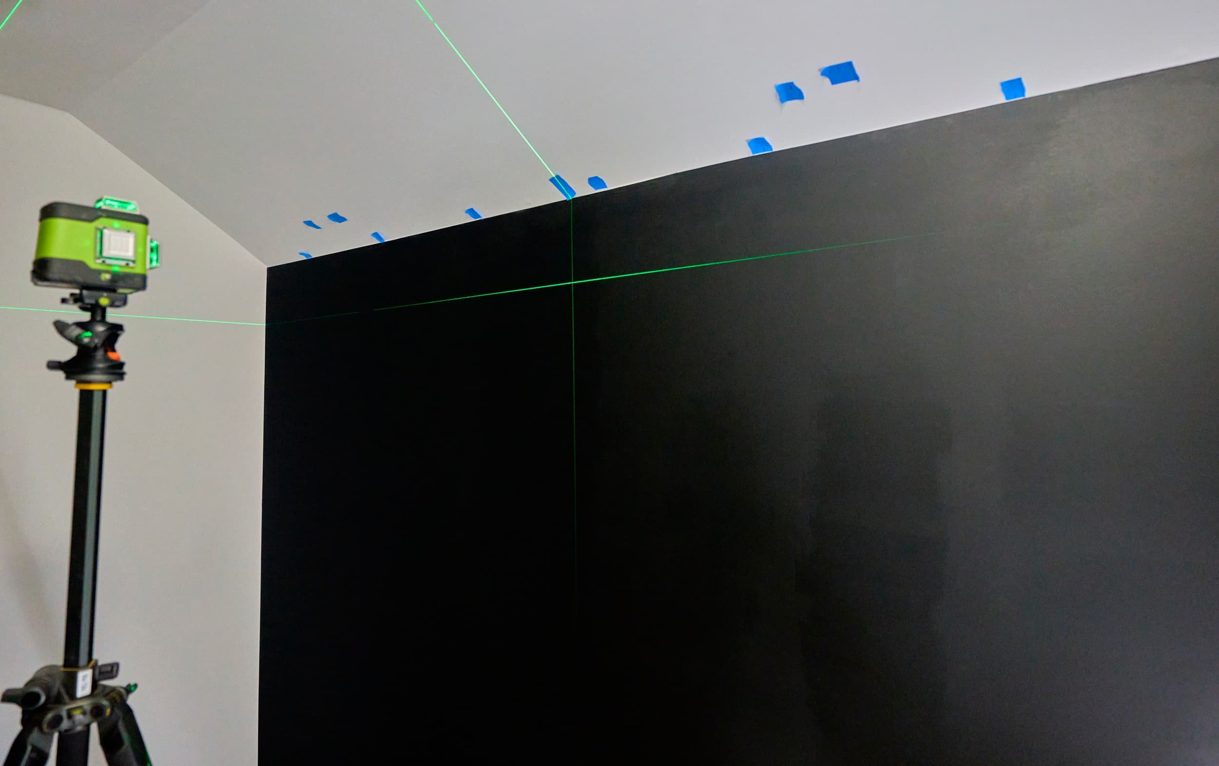
Step 1 - Painting the base layer
I’ve never painted anything that ‘mattered’ before in my life. Sure I painted the shop, but that was white-paint, on white-primer on white-drywall, and it’s a shop — it’s not required to be pretty. Here I am, taking a wall that islavender-ish and making it black. On a room with carpet.


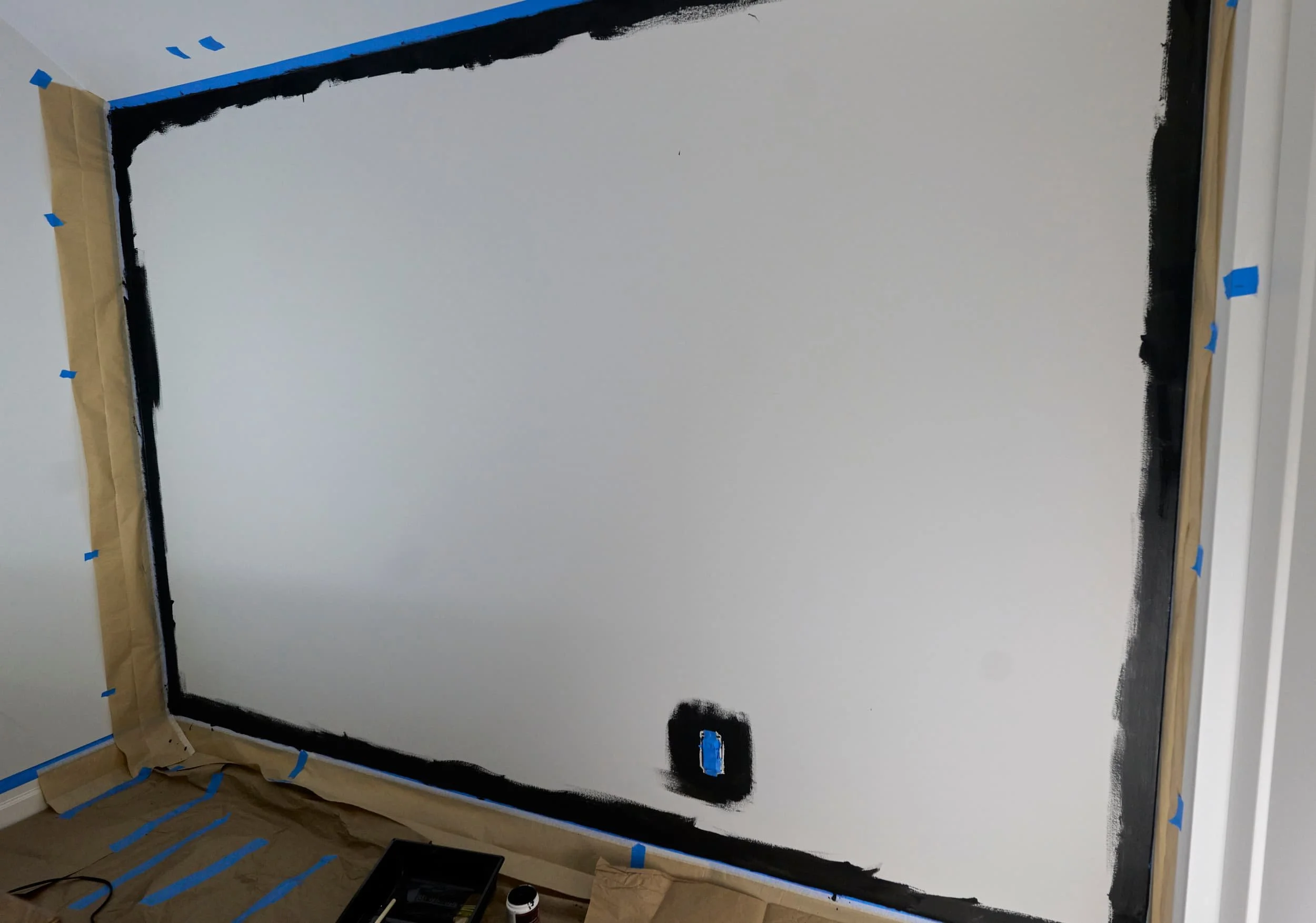

I went with Behr Marquee matte-paint in Limousine leather. My working area was about 70 sq-ft and I was told that the small can would give me about 100 sq-ft. When I bought it, I wasn’t sure if I needed two coats or not, so I picked up a tester as well just for a bit of buffer because I didn’t want to have to go back and get more paint mid-project. Spoiler: I didn’t need two-coats and I didn’t need the extra sample container.
For masking, I went with blue tape because I didn’t want to risk pulling off any good paint on the edges and I used a yolo mix of dollar-store artsy brushes, foam brushes, a cheapo bristle brush and random 10mm roller. No idea if my approach was right, but I think it turned out okay (and it’s mostly going to be covered anyways) and the most important thing for me was that I didn’t get any paint on the floor or walls.
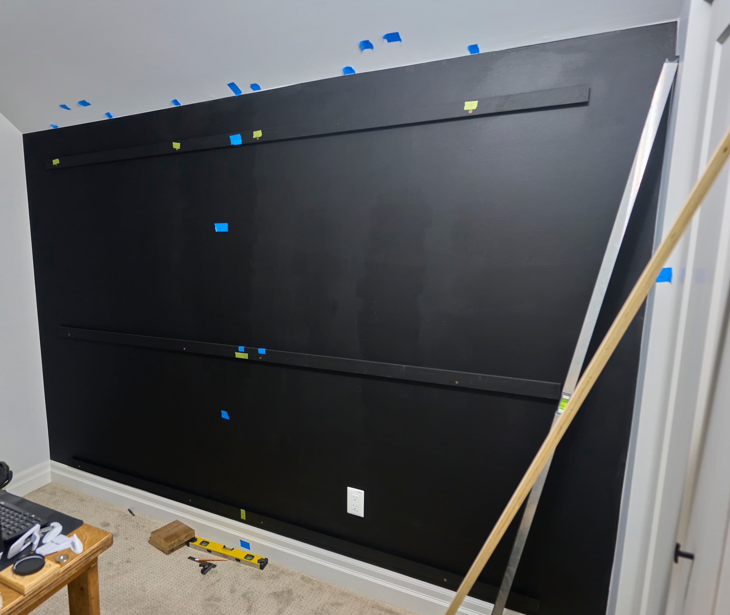
Step 2 - Making cleats
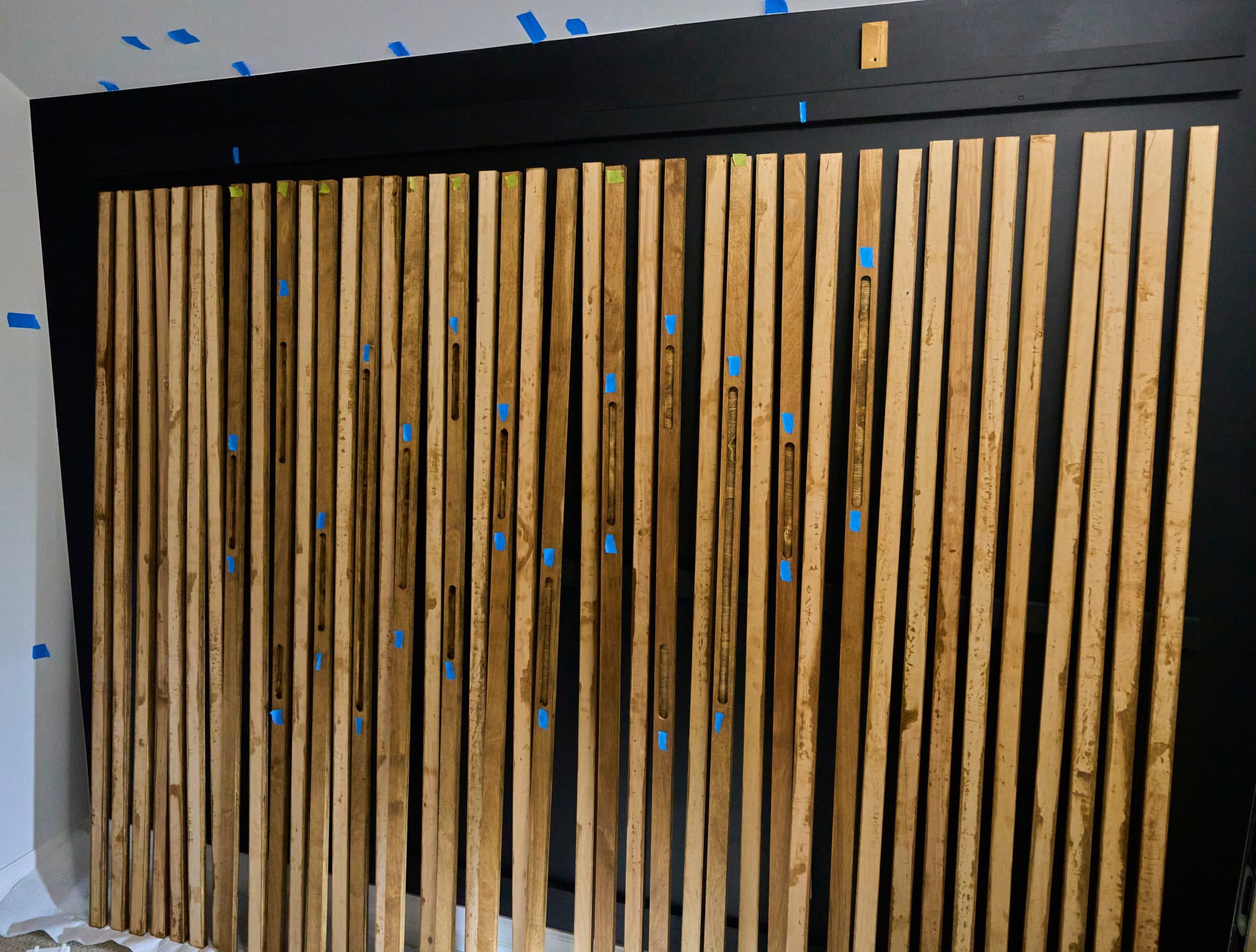
One thing that makes my wall a bit different from most of the ones online is that mine is [mostly] hung on a French cleats which means that I could remove the entire thing off the wall if I absolutely needed. In truth, I do have a middle brace piece that isn’t a French cleat and I did have to pin a few slats to that to keep them from wobbling, but the pins can be pried off if the need arose. In hindsight, I would have done three sets of French cleats so that I definitely could have taken it off the wall without effort.
I painted the cleats (and the screws used to hang them) black to make this blend away together.
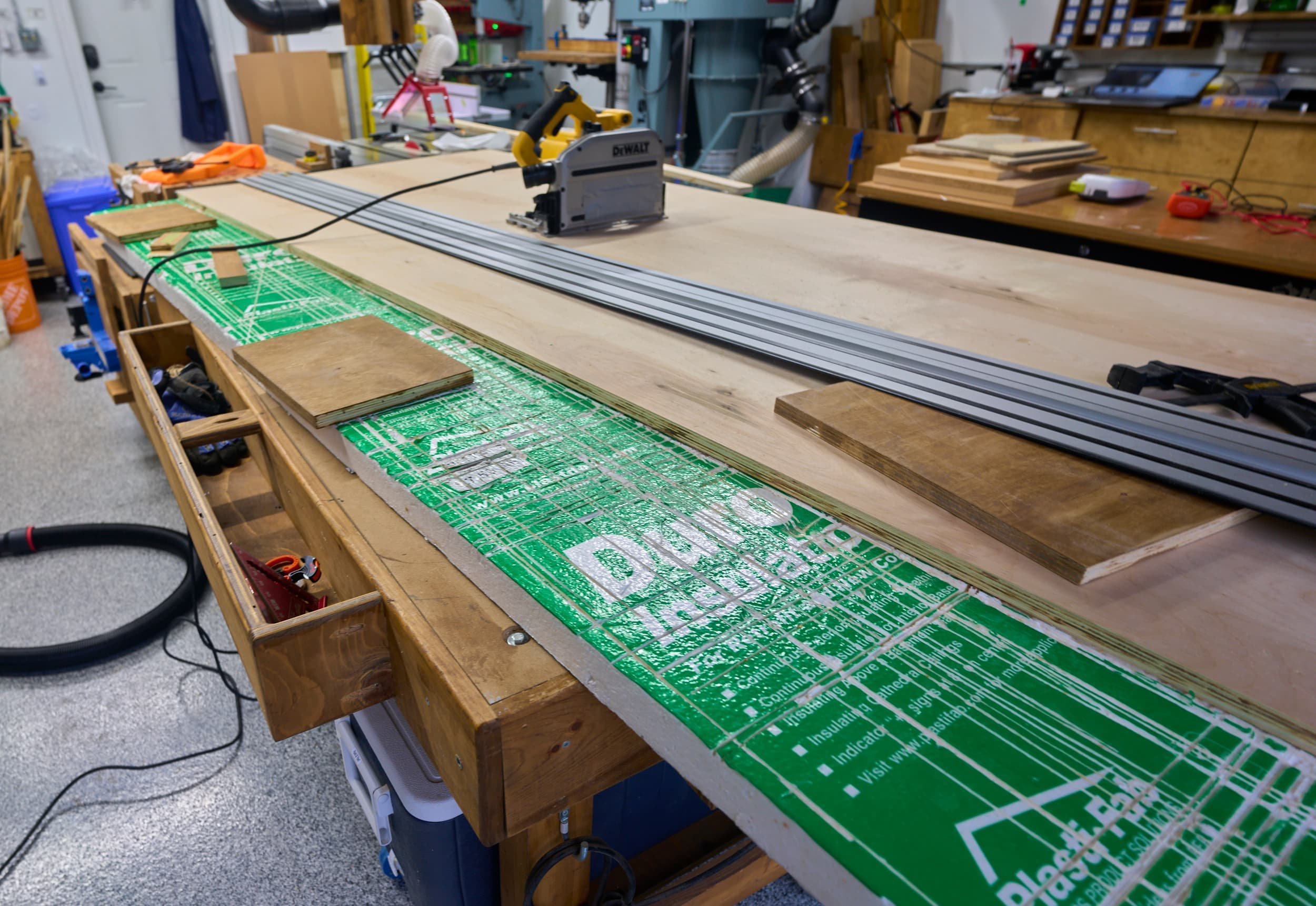
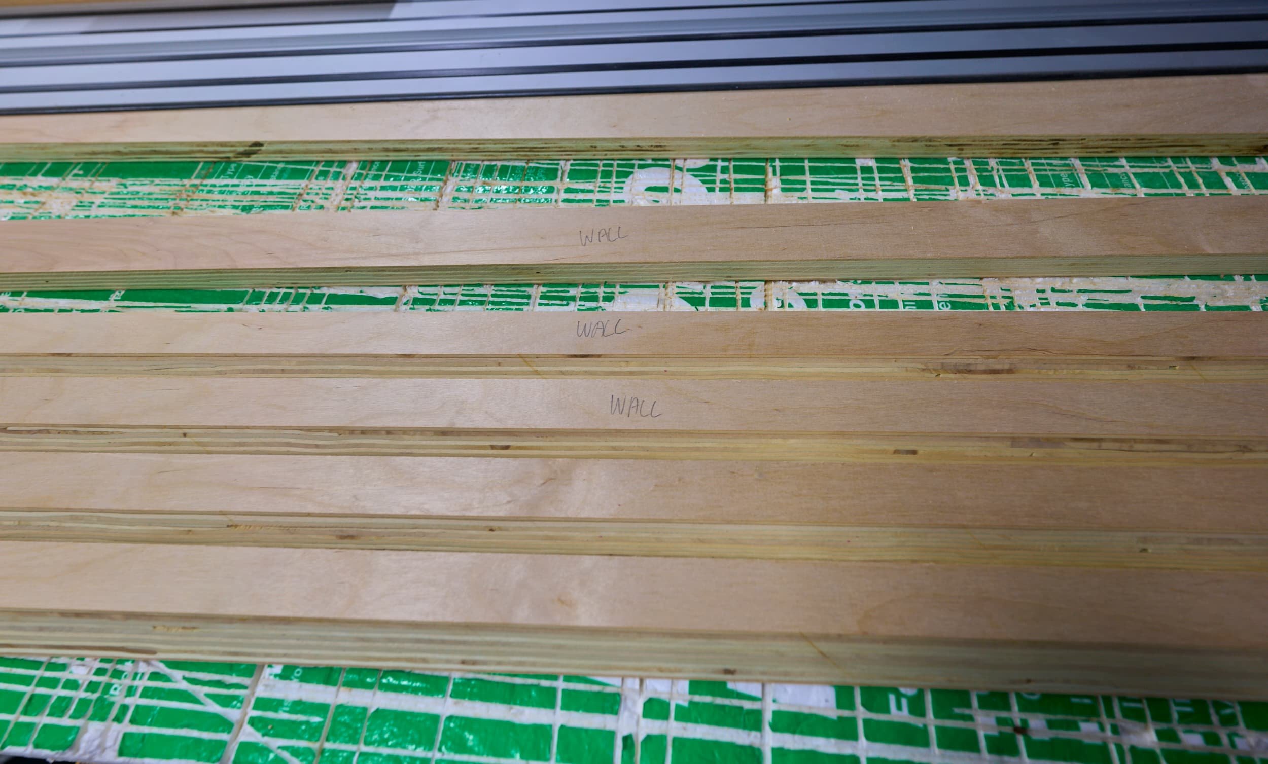
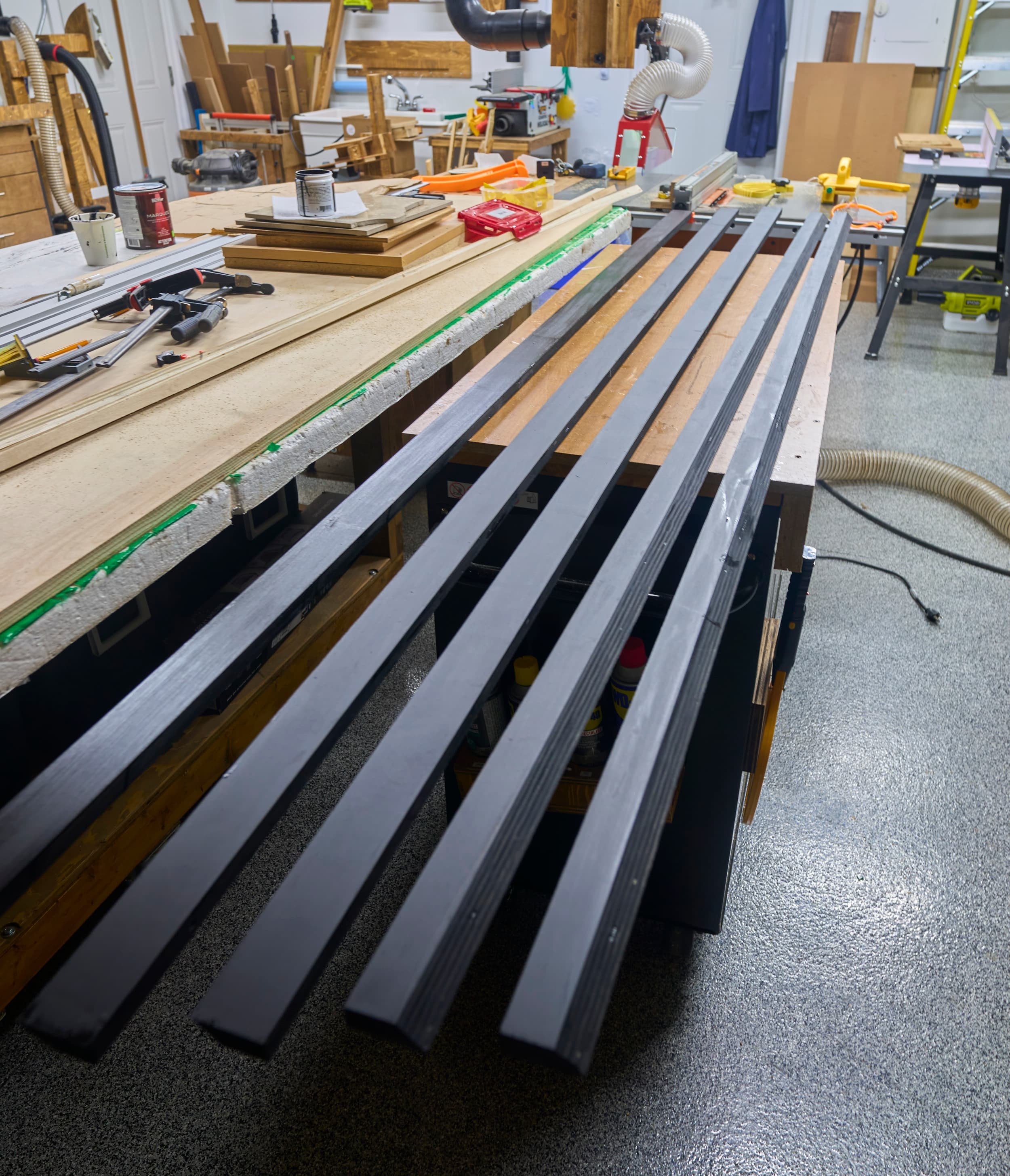

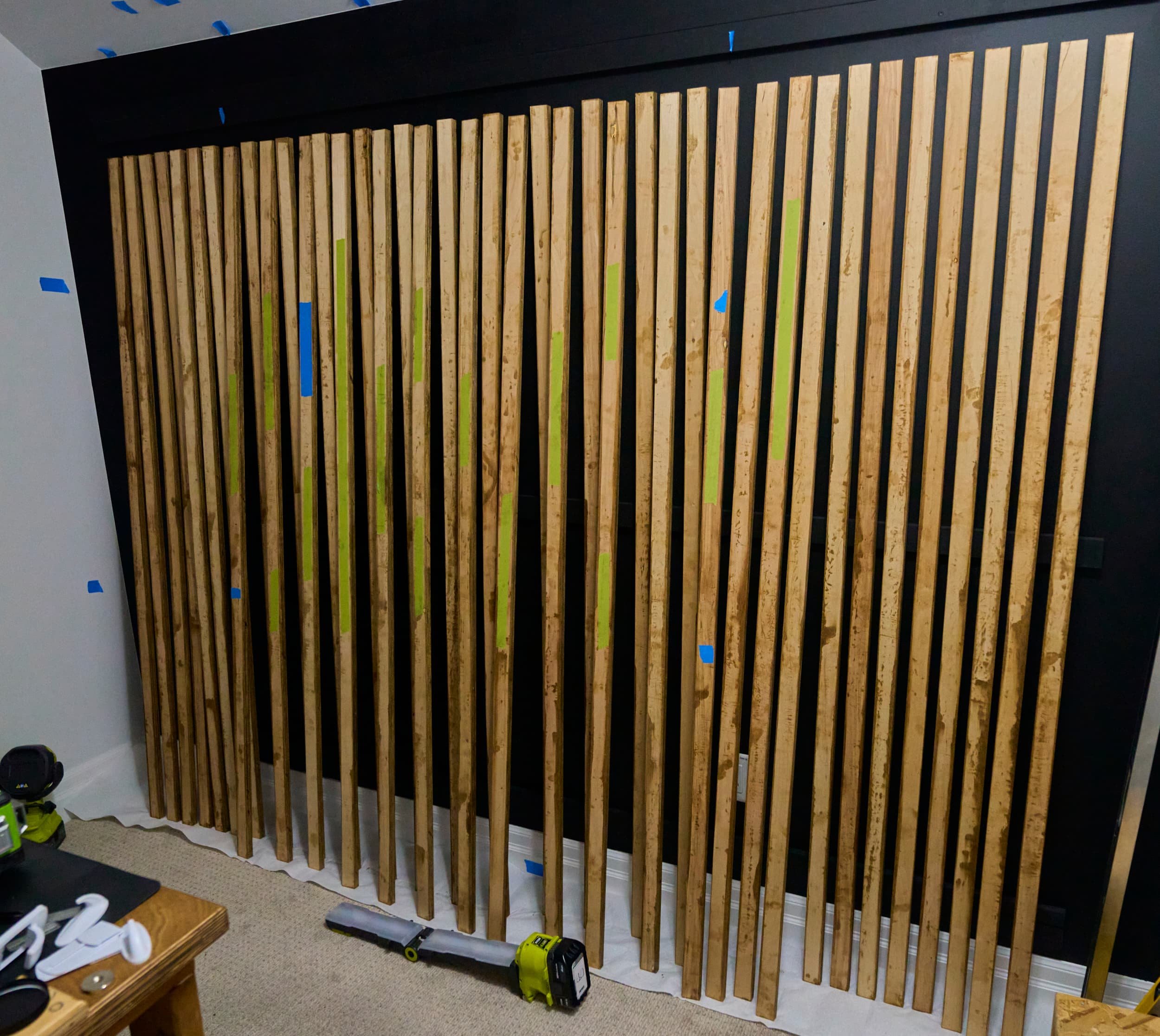
Step 3 - Making slats
At the start of this project, I had about 2½ sheets of ¾-plywood and I had settled on roughly 1½” wide strips with a ¾” gap between them; doing some math, I needed somewhere around 42 strips — depending on whether I was planning on centering the slats or aligning to one of the edges (and I guess, depending on how accurate I was with lining things up). Because I like to live dangerously, I opted to make 43 slats to give me a full extra spare.
I used the tracksaw to rip the plywood down to a manageable size and then batched everything out on the tablsaw. This was a bit messier than making all of the cuts with the tracksaw but it was so much faster and I could play into the strength of the table saw and get dependable cuts. I explicitly sanded all surfaces to 220-grit, in particular, going as far as batch-sanding the plywood edges together. Time spent here getting a smoother finish makes the staining process go so much faster (because you can simply swipe with a brush for coverage rather than having to go back over unsmooth surfaces).


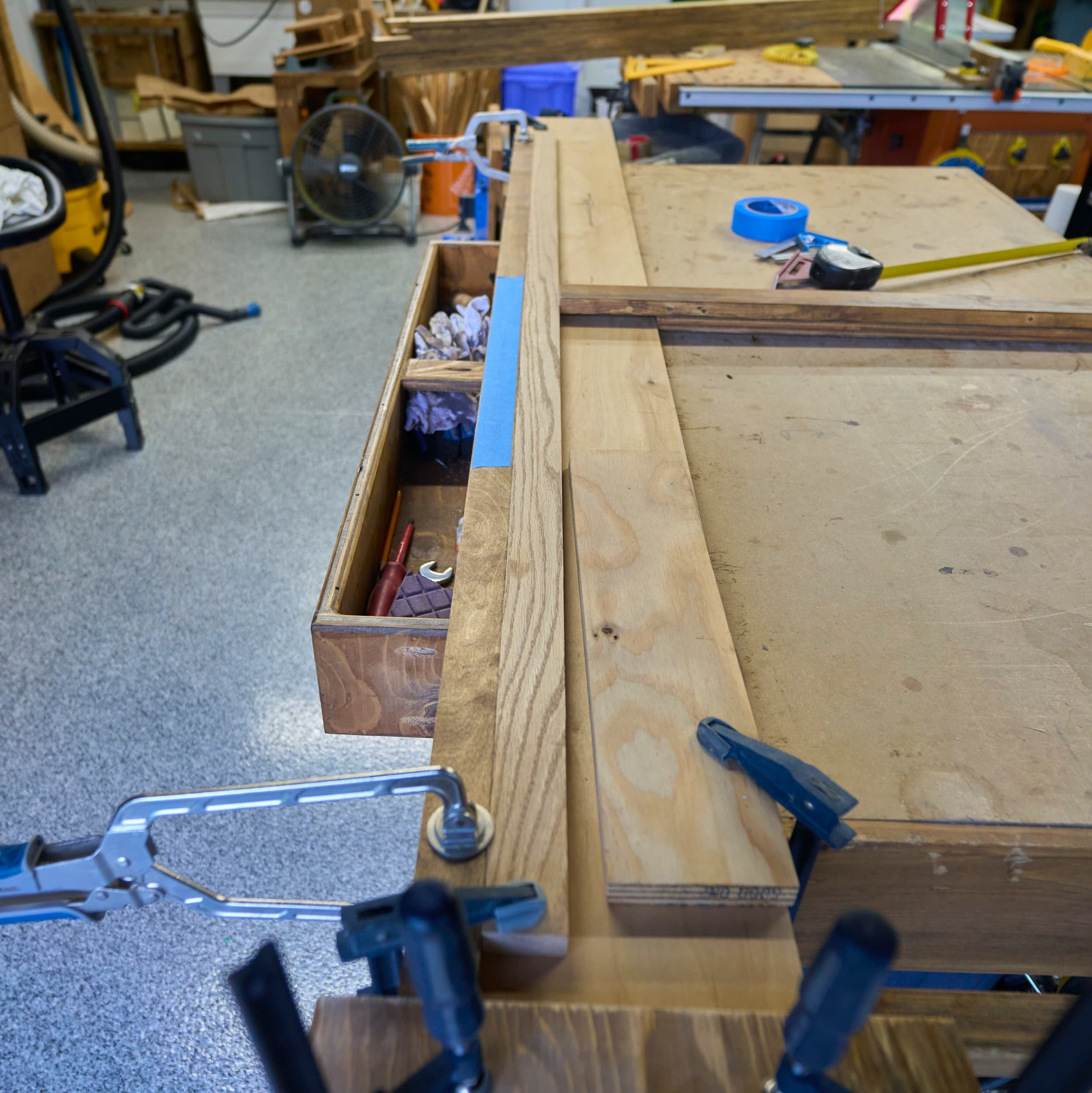
Step 4 - Routing slots for channels
An easy method to add RGB to the wall would be to surface mount the strips (either on the front or on the back, for glow) but I definitely didn’t want to do that. Another easy option would be to place the RGB channels in the gaps between the slats but the inconsistency would drive me mad. I could also put a line of RGB at the top/bottom/both running the width of the wall, that would be easy but it didn’t have the same cool factor.
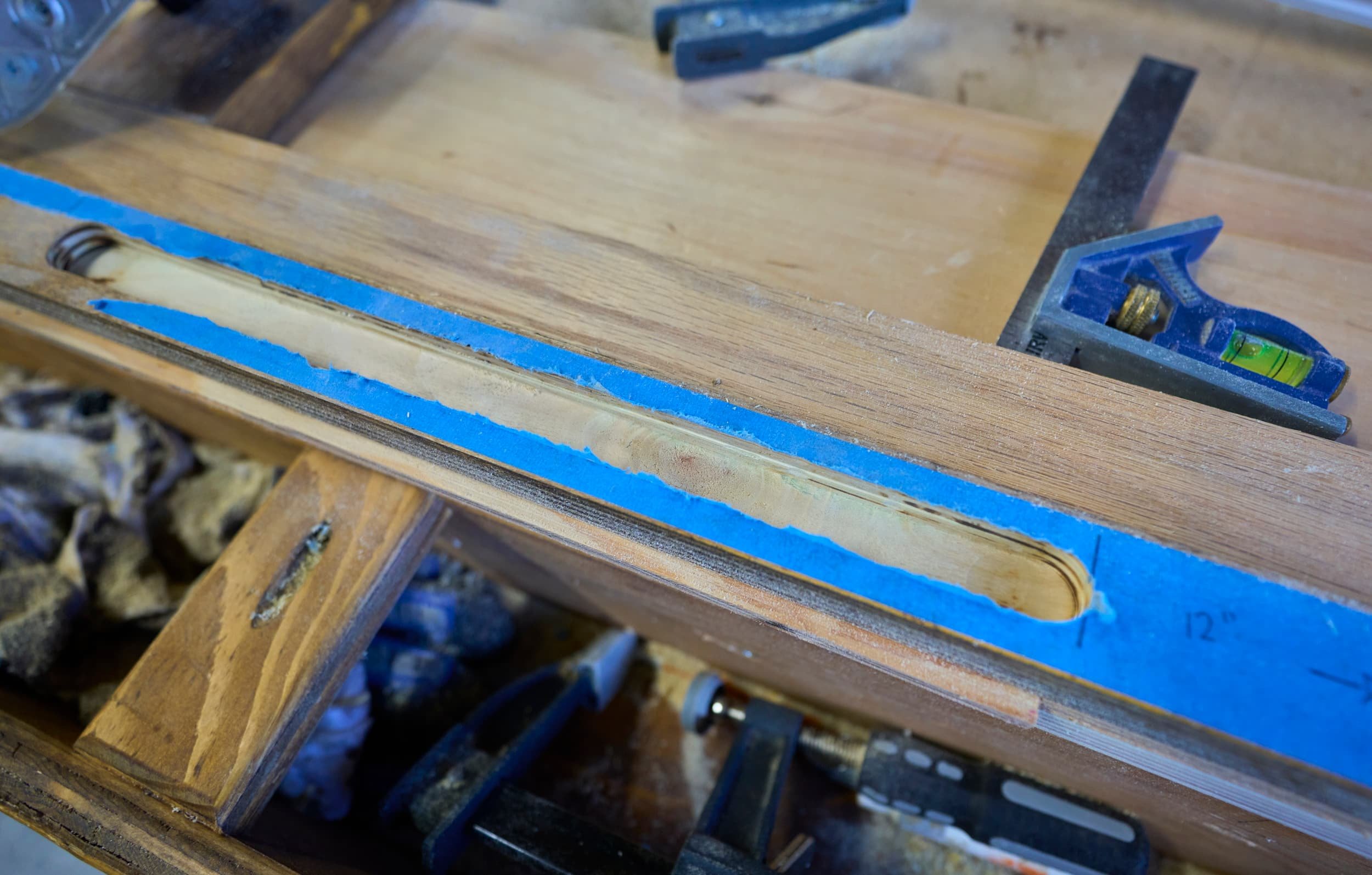
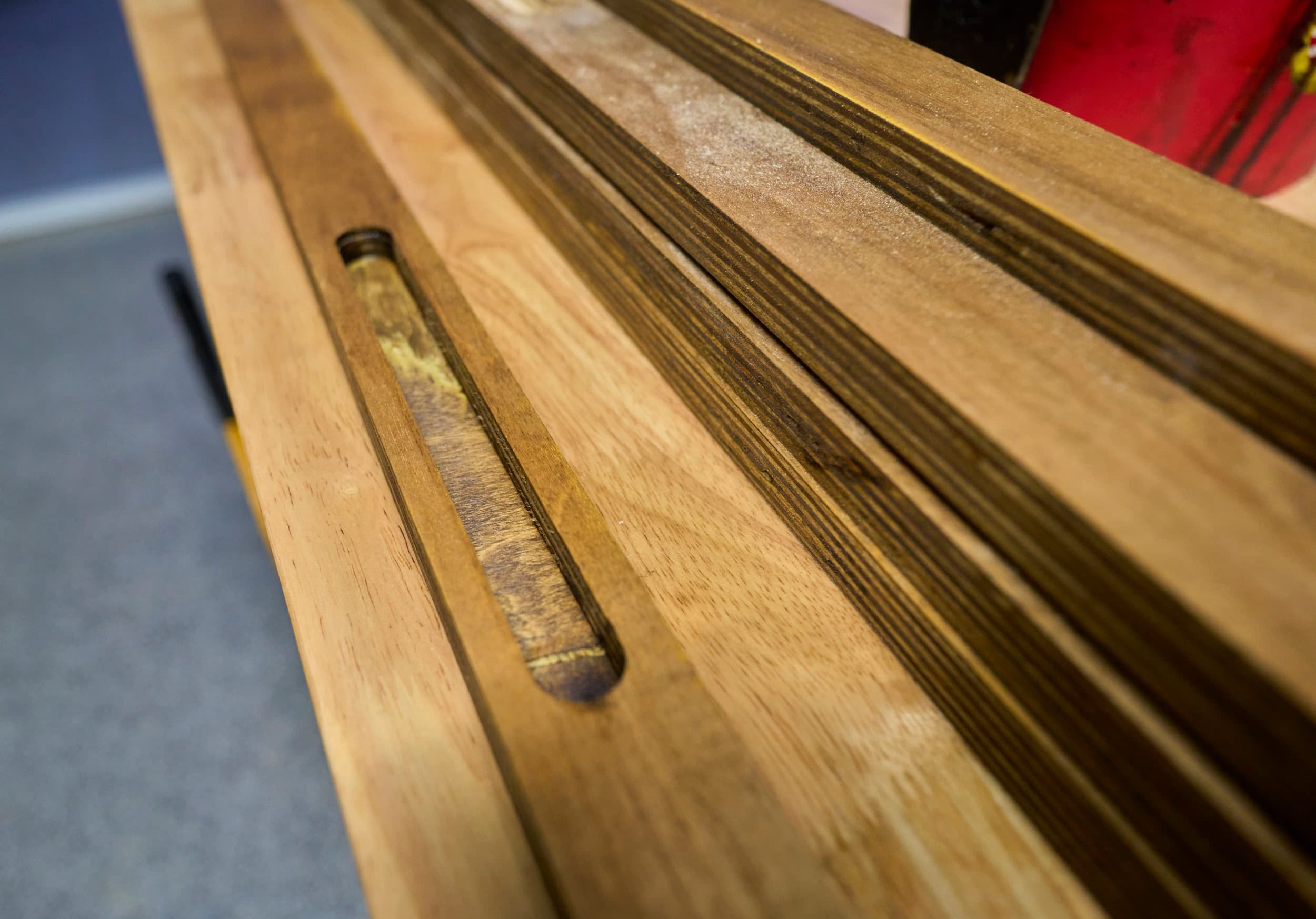
All this to say, I was going to route out slots in the front face to place the aluminum channels and then run wiring from behind. Not only that, it was going to be a bit of a ‘dynamic’ shape. I borrowed a router table and did a few cuts but it still felt hella uncertain (and I was on the clock for this project so 'testing around’ wasn’t viable); so after a few slots, I opted to setup a routing jig (since all of my slats are identically sized).
There is an argument for squaring off the corners of the slots but I opted to leave them round because [1] it’s less work and [2] the extra buffer area gives me room to drill a passthrough hole.

Step 5 - Wiring RGB (aka misery)
Now that I’m done the stressful part of routing out slats, I thought this would be the easy part. I thought that the very first connection would be the hardest; sadly, it turned out to the be the easiest and most straightforward.
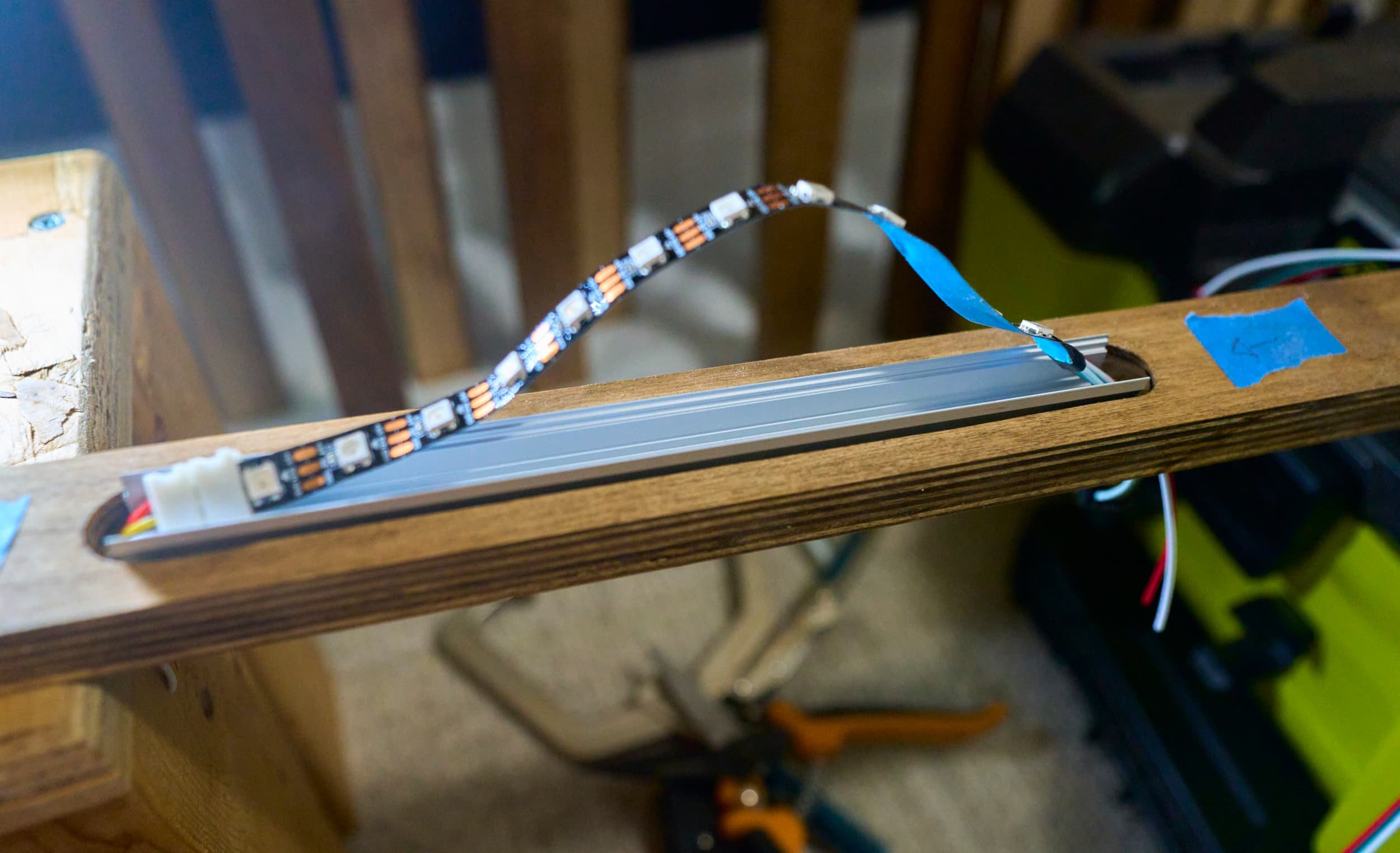
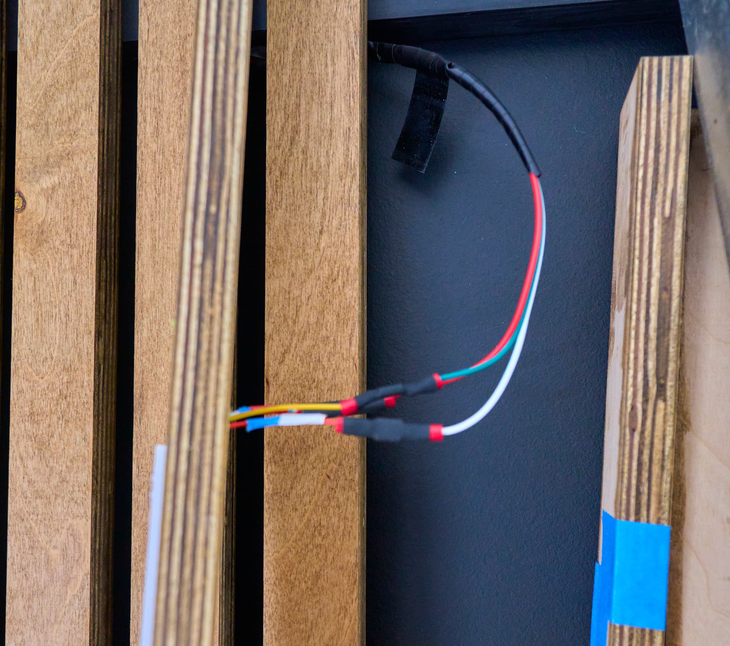
Initial connection from wall to RGB strip
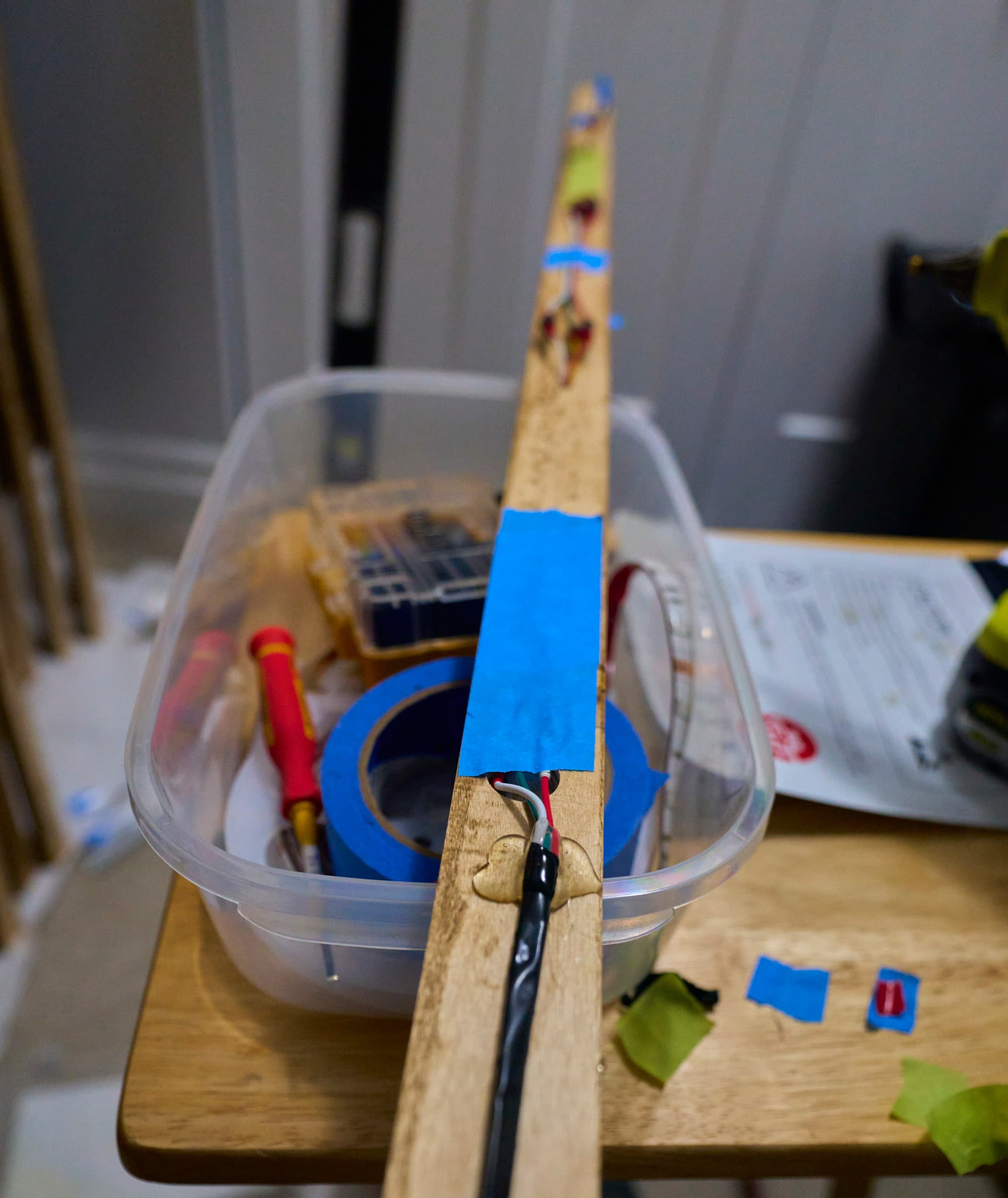
This was pretty straightforward and I was in high spirits: on one end (of the JST connector), I put spade-connectors which allowed me to run a custom length of wire between the start of the RGB strip and the controller.


For the first connection, I didn’t have to worry about connecting anything to the RGB strip itself — it came with a pre-connected wire. I thought I would save some time and make it so that I could easily replace burned out sections of RGB down the road by using solderless connectors. Buy cutting the solderless connector in half and using spade-connectors, I could insert a custom span of wire which would allow me to wire up the RGB strips up and down the slats. Again, at a high level, this looked a bit tedious but certainly not problematic.
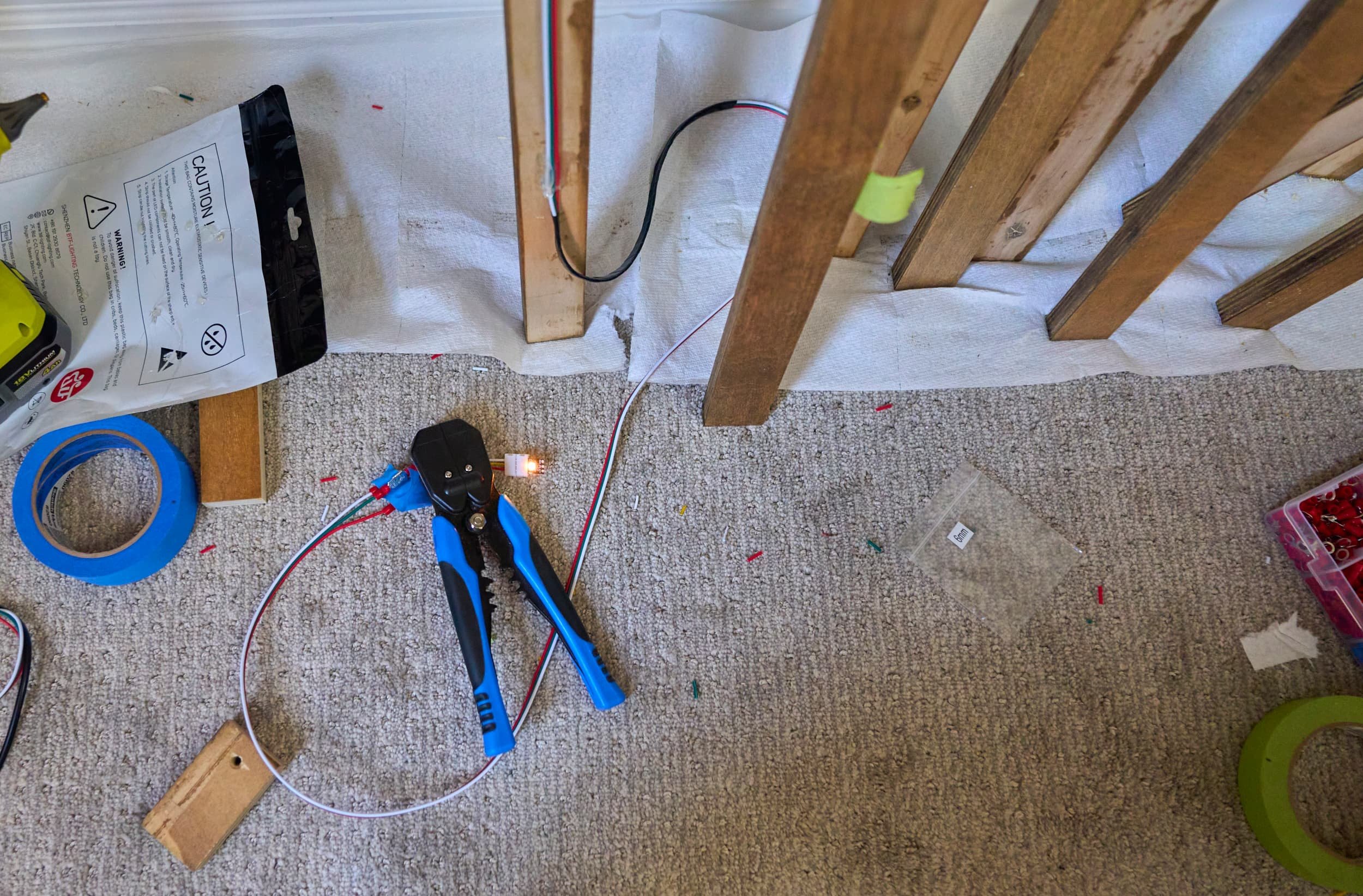
Leveraging the solderless connector with spade bits to make custom length quick-connections. What could go wrong?
I figured for the nest few hours, I would go through the following process:
Determine the length of the RGB strip needed, cut it to length
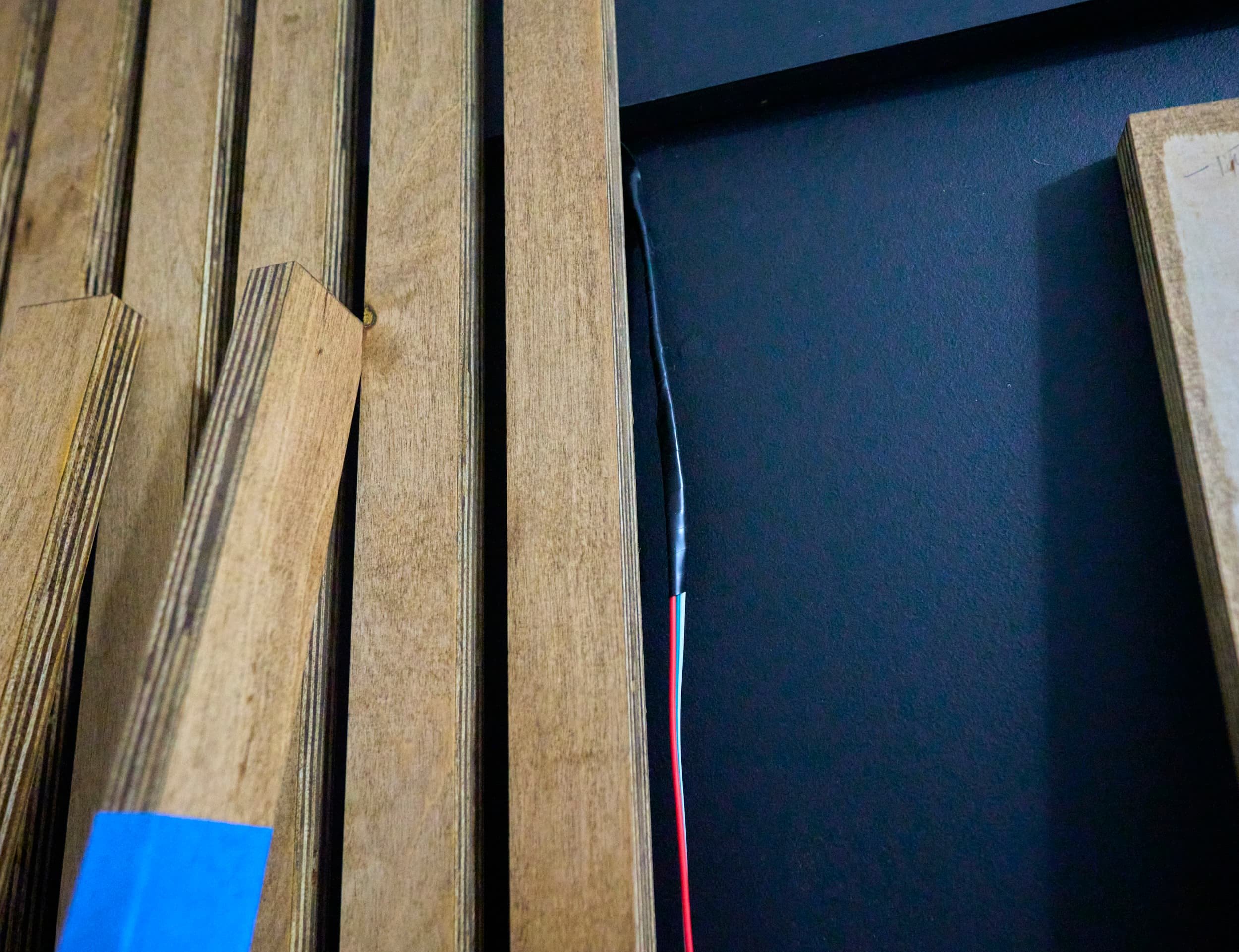
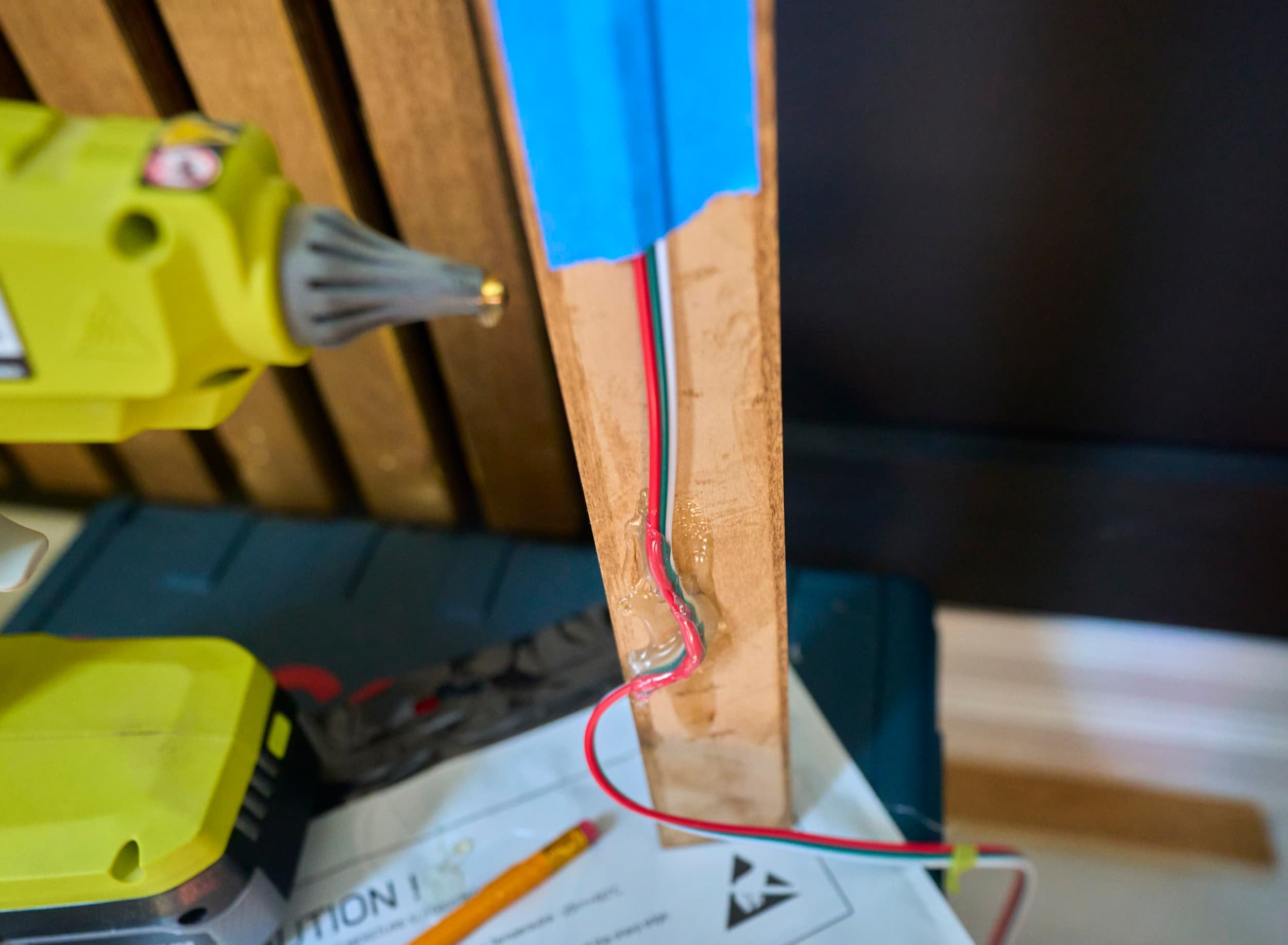
Drill the necessary hole in the slat to pass wire from front to back
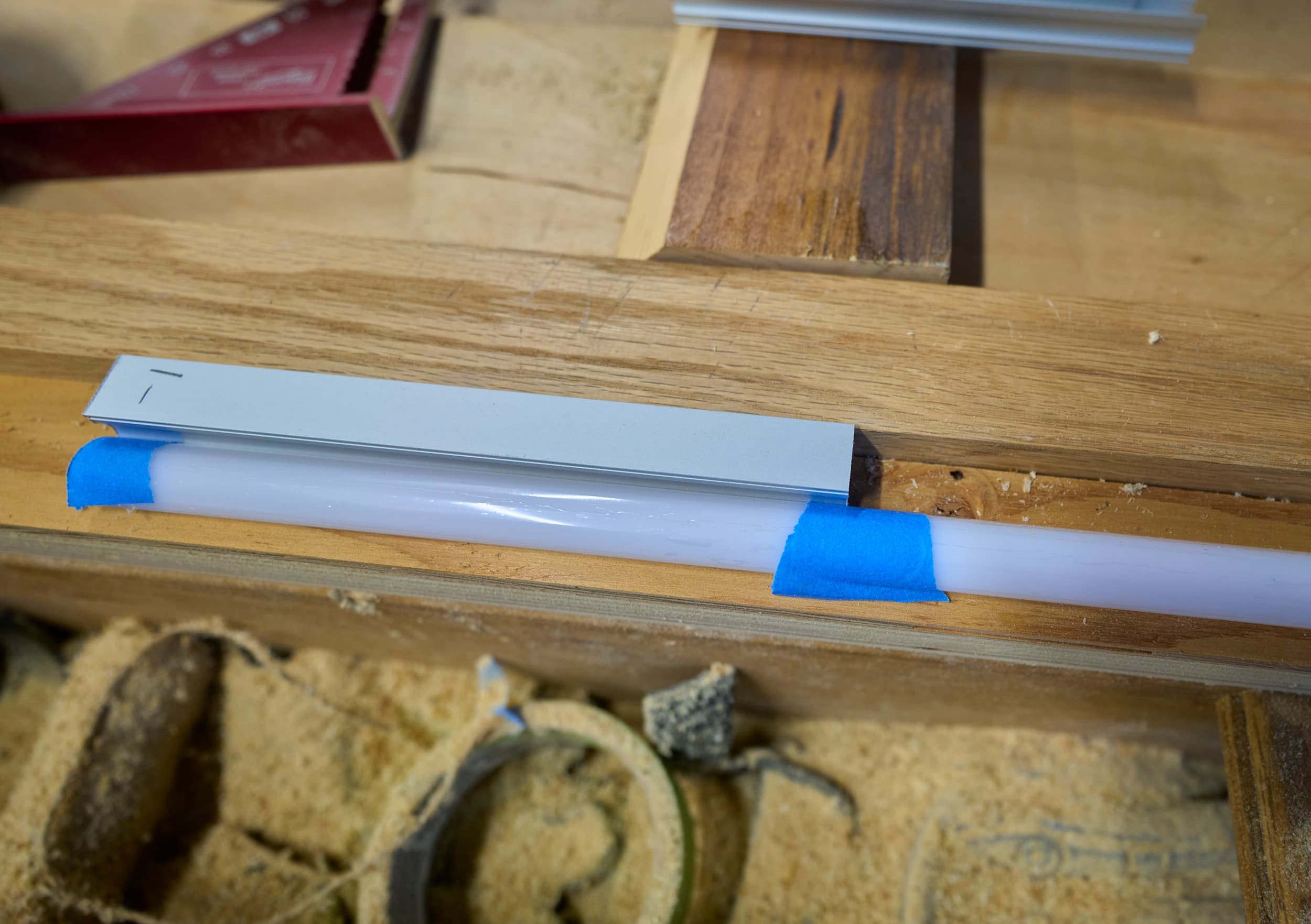
Hot glue the aluminum channel in place
Cut a solderless connector in half, feed it through the hole, add spade connector to it, clip the RGB strip into the solderless connector
Take the other half of the solderless connector, feed it through the downstream side, add a spade connection to it, clip the RGB strip to the solderless connection
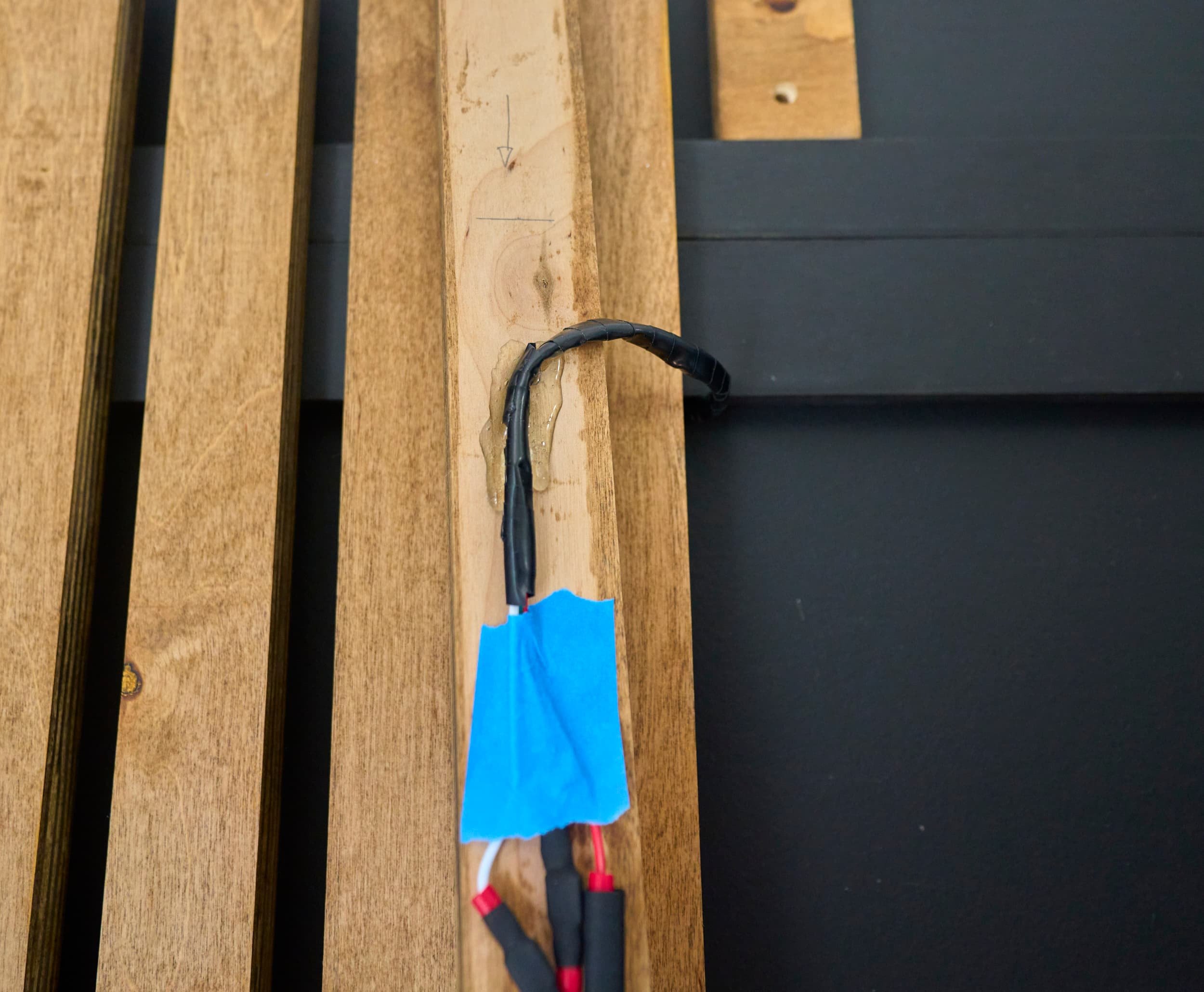
Verify everything works, add heatshrink to the space connections (to keep it from shorting out), tape the light down, pin the slat on the wall
The first few slats (with RGB) mostly worked out like this and then suddenly, I would see some extremely odd behavior: the last few strips would refuse to light. If you cycle the power, there would be a 50% chance it would work. I initially doubted my crimping job — maybe the crimp connectors were having a hell of a time dealing with 22awg wire? So I busted out the multimeter to check continuity and voltage and then discovered my second oddity: there’s no continuity on the data line! Like even between two adjacent RGB nodes.
I would made very painful progress (about 1-hr per light segment): things would work, they would stop working, then they would look like they worked but when you try and change the color (testing the data signal), some LEDs would not change. I crimped and recrimped several connections a few times; I even switched my connections entirely to spade crimps; I thought I would save time and material in heatshrinking by using the inline-coupler crimps — but I needed the spade connection so that I could take things apart to troubleshoot.
I eventually got smart and chopped a single LED and put that on its own solderless connector with spade connections on it. This is where things got extra tedious. Every time I would do anything — connect, disconnect, heatshrink, run a wire, etc, I would have to power things up to make sure ‘things still worked’. Progess was extremely slow here because I would finish a few slats… just to have a slat that was ‘known to be working’ stop working and I’d be back at square one troubleshooting connectivity.
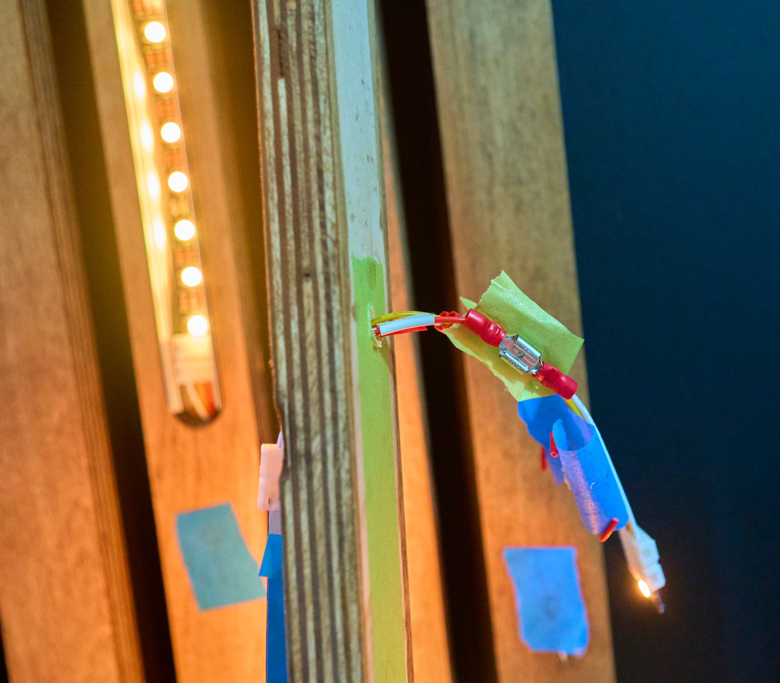
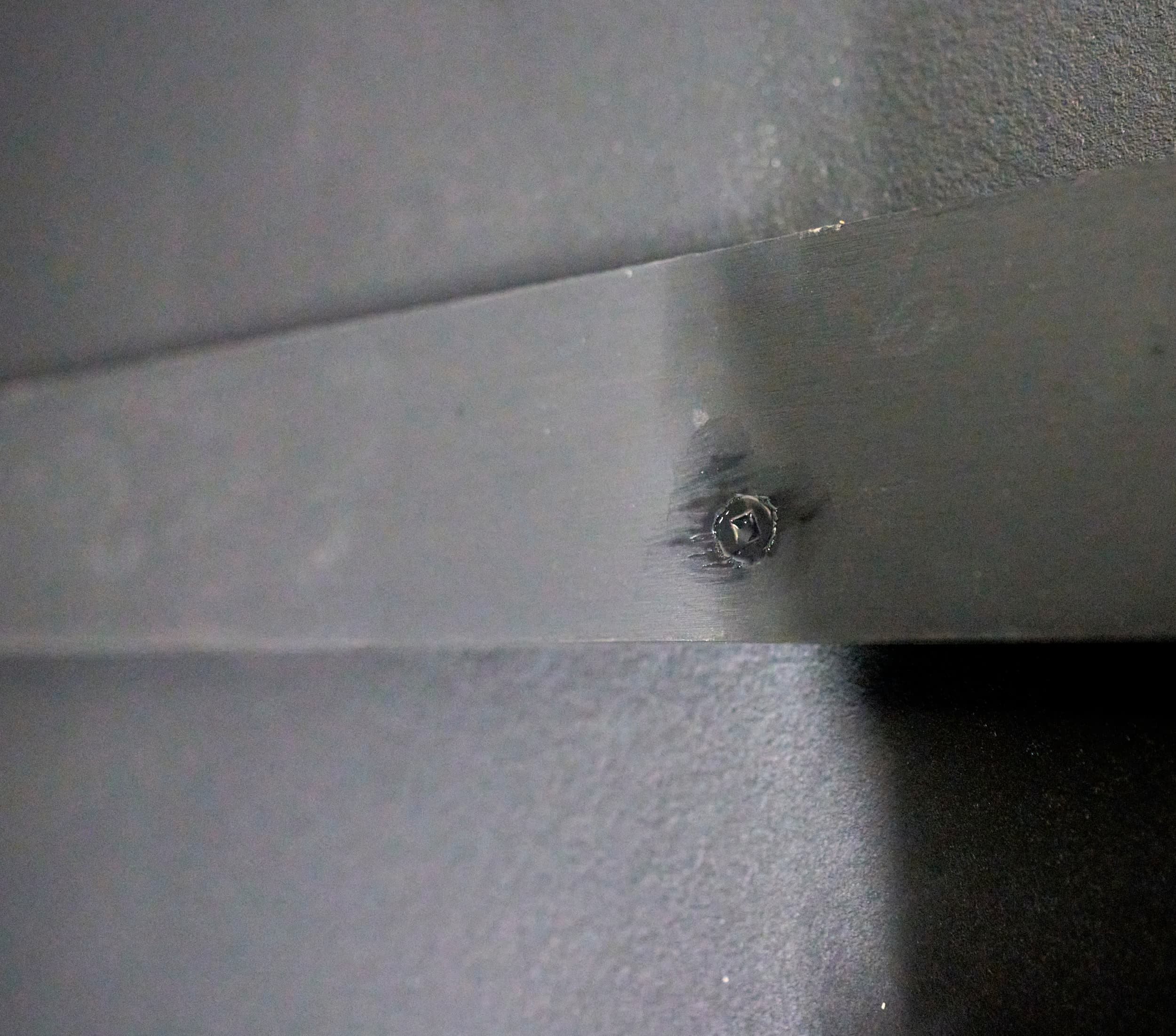
I eventually discovered that the problems I was having was entirely because of the solderless connectors. In this magnified shot, you can see the metal contacts that slide over the copper connections on the RGB strips. This was an exercise in extreme frustration as I did troubleshooting.
I verified continuity from the copper contact to the far side of the spade connector. Good tone. This means that each copper contact is touching the prong and there’s a solid connection from the metal prong all the way to the spade connector. I verified this for all three copper contacts
What if the springy connector is lifting off? While there was power in the system I used a small screwdriver to gently mash the connector onto the contact. No change. I used three screwdrivers to carefully mash all three contacts (without touching each other no less). No change.
I tried flicking the connector. I tried squeezing gently. I tried squeezing hard. No consistent change.
I tried re-seating the RGB connection. No dice.
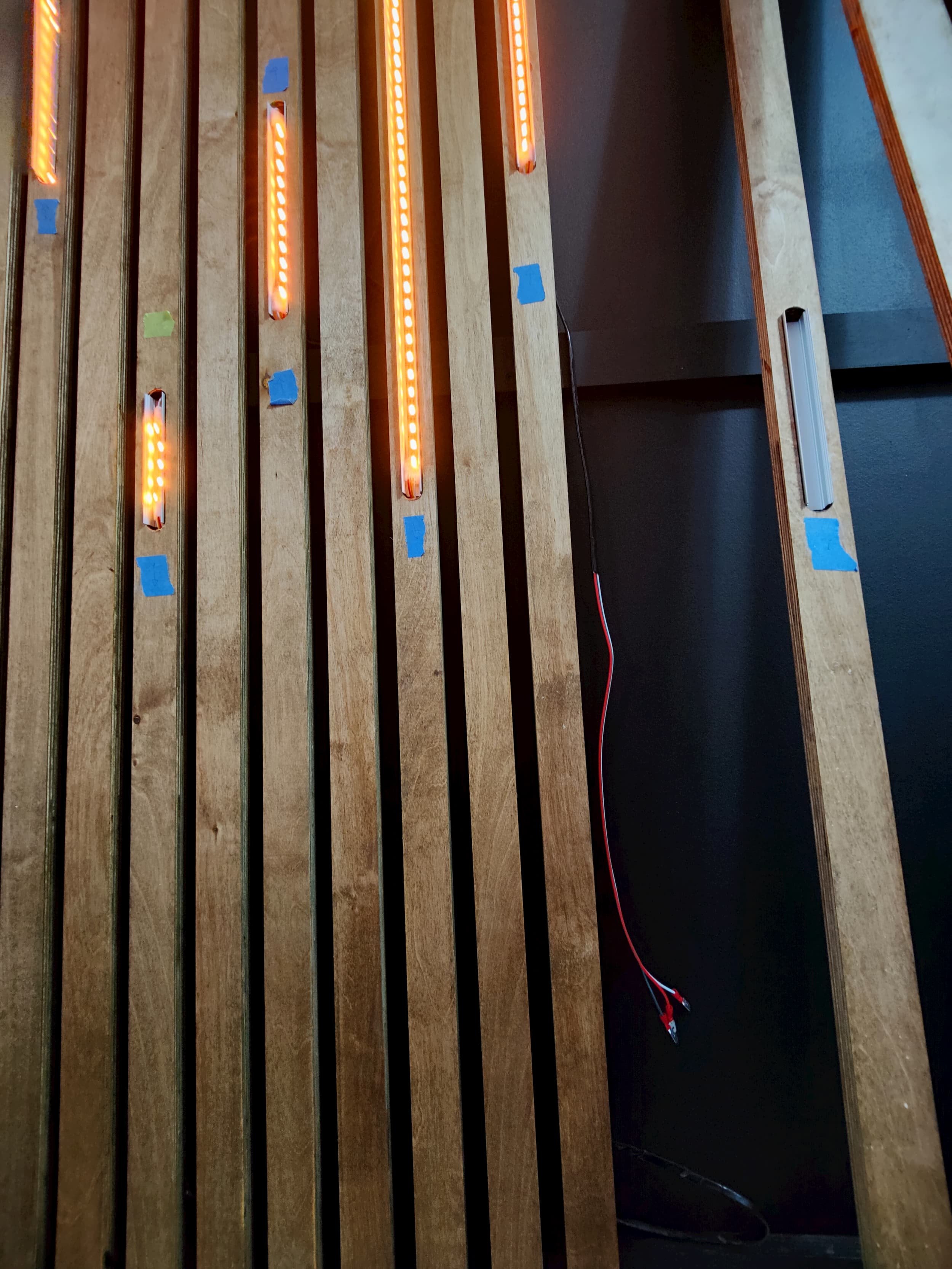
Also, nothing at the time could explain why things would work/not-work and then, with a power reset, they would not-work/work. I would later deduce that just because something lights up does not mean it’s working. I found that the best test was to set a scrolling animation: for an animation to work all three pins (power, ground and data) needed to have a good stable connection— if any given segment stopped animating, then you knew something was up and you could tell where it had fallen over.
This extra knowledge was helpful but also extra infuriating because things would work for hours (including full color changing animation) and I would cycle the power (using a power bar as to not disturb any wire connections no less) and there would be a random break. Upon closer inspection I did discover one (of the two!) problems: when cutting the RGB strips, I had cut slightly poorly on one of them so the copper contact was substantially smaller resulting in intermittent disconnects.
Fixing this was a fairly easy (and fortuitous) fix: I happened to have enough leftover RGB that I could swap out the ‘misbehaving’ length with a longer one where I intentionally cut it poorly (but in favor of making sure there was enough copper). This led to the second ‘discovery’: even when there is a good contact patch, everything is cinched down, there’s continuity, the damn connection still doesn’t work.
I had discovered there was a specific connection where you needed to pinch the solderless connection with a certain amount of force. Too little or two much and there wouldn’t be a data connection.
At this point, I just gave up.
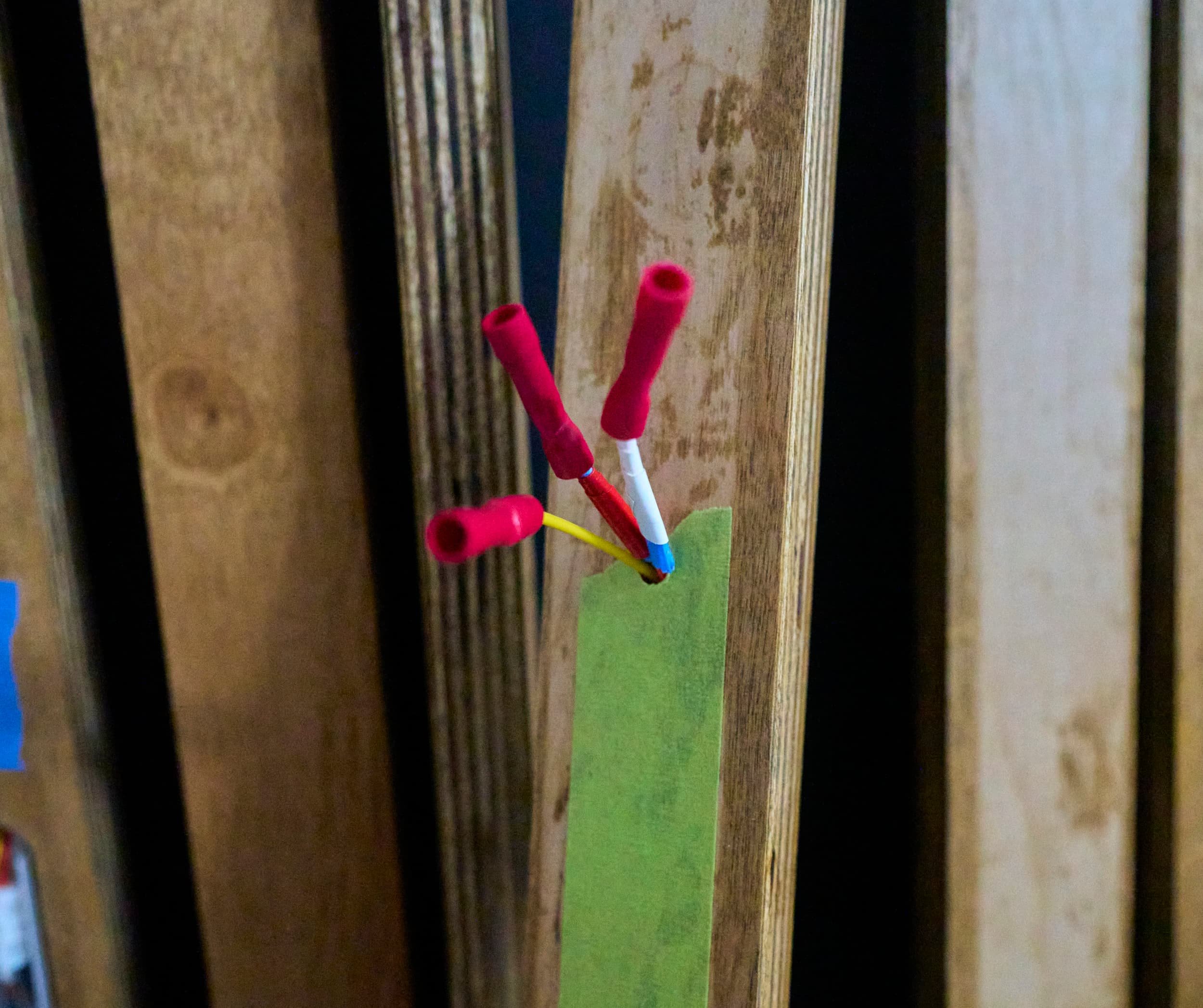
I took a yellow and a blue crimp connector, broke off all the metal bits (to prevent accidental shorting) and wrapped them in white electrical tape (to not throw off any coloring). I put the blue one behind the solderless connector and I put the yellow one in front and forcibly jammed the channel’s diffuser on top of it. That was enough force.
Why not solder?
I debated this (and at one point busted out the soldering iron to do a quick test) but I really like the ability to unclip a section of RGB and plug in a new one if it fails — this was certainly something I did during troubleshooting as well. Can you desolder? Yes, but there’s an additional complication the aluminum channel wasn’t wide enough to fit the quick connector in place (which didn’t help things) — so I had to put things on an angle (and soldering on an angle in a cramped channel was a no go).

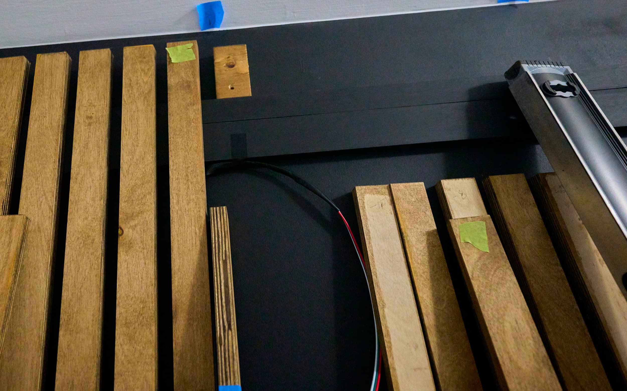
Working around the power outlet
To work around the outlet, I simply chopped that the slat (with a generous margin) above and below the outlet. I specifically placed the French cleats and support brace at altitudes with this in mind. For the segment below the outlet, it’s a short enough run that it would just hold on its own and the main section above the outlet was close enough to the brace that I could just pin it to the brace without introducing extra ‘wiggle’.
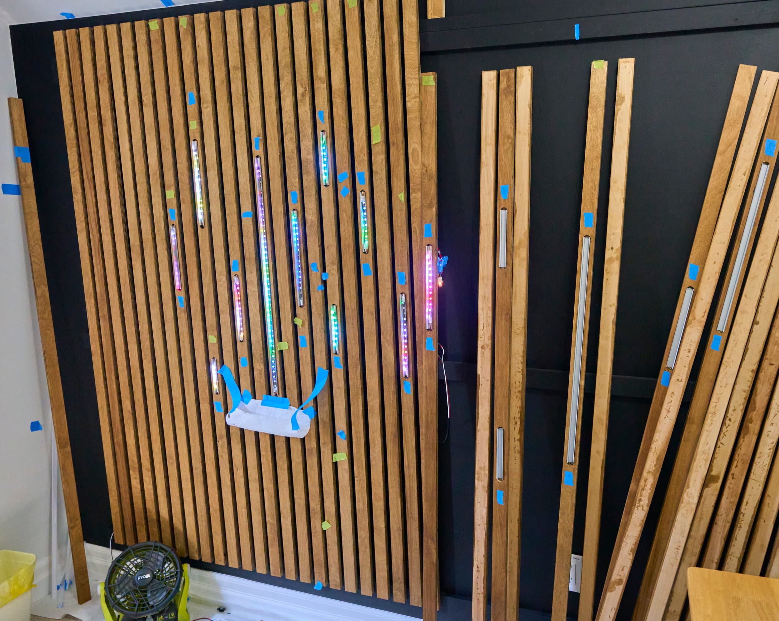
Milestone
With the exception of a couple fiddly connections and the fact that the strips took way longer than I wanted, this was a reasonable success. Nicole gets a bit of a refresh on the room, there’s cool factor and the extra width of the backdrop means that I’ve got more flexibility on where I can place the camera. And technically speaking, I can still hang a curtain-style backdrop if a specific need arises.
Using WLED to control the LEDs is a breath of fresh air though: there’s so much you can configure and everything works snappy fast because it’s all local to my home network. There’s an almost overwhelming colors, effects and settings to play with but it’s all laid out in a very friendly way.
All done (for now…)
Mixups, surprises and lessons learned
By a landslide, the biggest grief point was working with the ‘quick’ solderless connections. In their defence, it doesn’t help that the connectors don’t fit neatly in my aluminum channel which required me to put them in on an angle. This additional rotation introduces a pull-out force that the quick-connnect needs to resist (and intermittently fails to do). Lets look at some sizes:
My RGB strips are 10mm wide; at the very start of the run I have a pre-attached power lead. The connection (mostly heatshrink) makes the strip 10.2mm across at this point.
Fully closed, the quick solderless connector is 14.5mm across; when open enough to access the RGB strip, the connector requires 14.8mm clearance.
It’s possible for the solderless connector to clip in neatly at the top of the channel — but then I’m unable to slide/clip the diffuser over it. I suppose I could cut out a small relief on the diffuser to allow it to slide over, but I didn’t think of it while I was putting this together and there’s always the risk of shattering/cracking the diffuser.
Just brainstorming, I think that switching to super deep V-channel (18.4mm internal width) would have solved all my problems:
Wide enough that I could even consider putting in two sets of RGB strips; obviously wide enough to fit the quick connectors without fuss
Tall/deep enough design that the diffusion would still smooth out the LEDs
The only change I would have to do would be to route a V-groove rather than a straight/wide groove. To fully recess this channel, I would need to route roughly 21.3mm down. I could probably get away with something slightly more shallow, say 20mm.
This functionally means that I would be routing entirely through 3/4” plywood. At the top, I would need to be roughly 42mm (1-5/8” wide!) across. I could probably manage to do this if I increased the width of the slats to 2” or so. Being entirely through-cuts, I could probably use the table saw to cut this a bit more safely.
There is a less-intense V-channel, which would only require routing 11.3mm down and being 22.6mm (7/8” wide) across. This would be a lot easier to route, but the diffusion would be notably less.
If I was better at soldering (in tight confines no less) then perhaps soldering lead wires directly onto the RGB strips would be the way to go. By including a bunch of slack, there would be enough room to pull the strip out and replace it if needed down the road. I could still leverage spade or molex crimp connectors behind the scenes as well.
One definite advantage here is that I would be entirely working with 18-gauge wire which is so much more pleasant to work with than the 22-gauge wire that the solderless connectors used. I might need to use some kind of cable clamp on the back side of the slat to keep the extra loose wire in check.
In hindsight, another option would be to just throw entire RGB strips at the problem: each RGB strip comes with a very nice to work with initial connection pigtail (that I could just use spade connectors with). I would simply buy a whole bunch of shorter RGB strips and chop them down to the length I needed, discarding the excess (I would save the excess bits for different projects that were less fussy). I could even go with brighter/smoother 100 LED/m strips. Of course the downside here is that it would cost a lot more. But given how much I swore during this project, it might have been worth it…


Appendix
Electronics
WLED compatible controller
5V 10A power supply
5m 60 LED/m RGB strip
18-gauge, 3-color wire. For my specific wall, I ended up needing to order two of these
The solderless quick-connects. I ended up chopping these in half — when I bought them, it was cheaper to do this than to buy the ‘single end’ version. You can figure out how many you connections you need based on the layout of RGB segments: you’ll need one at each end of the RGB segment
A boatload of spade connectors. Each end of a connection requires three pairs of spade connectors
Also a boatload of heatshrink. The specific spade connectors I had on hand were not fully insulated so I used heatshrink on all of the connections to keep them from touching
Woodworking, construction and tools
Roughly 1.5 sheets of plywood for my specific space
1 quart of paint + primer in one, I went with a matte limousine leather
23-gauge pin nailer to initially hold the slats — they are strong enough to hold the slats but if you need to, you can brute force pull the slats out
18-gauge brad nailer to really really secure the slats
a hot glue gun to secure the aluminum channel to the grooves as well as keeping some wires from flopping
a heat gun to work the heatshrink
Product links may be affiliate links: MinMaxGeek may earn a commission on any purchases made via said links without any additional cost to you.